


5 Maintenance Model 7300A
5-4
Teledyne Analytical Instruments
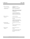
Table 5-1: Self Test Failure Codes
Power
0OK
1 5 V Failure
2 15 V Failures
3 Both Failed
Analog
0OK
1 DAC A (0–1 V Concentration)
2 DAC B (0–1 V Range ID)
3 Both Failed
Preamp
0OK
> 0 Amplifier failure high offset (number is a code
that pinpoint which gains are at fault).
Detector
0OK
1 Failed (open filament, short to ground, no
power.)
2 Unbalance (deterioration of filaments, blocked
tube)
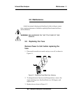
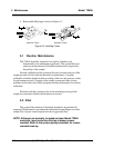
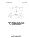
5.5 Major Internal Components
All internal components are accessed by unbolting and pulling open the
rack assembly, removing the front cover, as described earlier. The major
internal component locations are shown in Figure 5-3, the cell block is
illustrated in Figures 5-2/5-3, and the fuse receptacle is shown in Figure 5-1.
The 7300A contains the following major internal components:
• Customer Interface PCB (Power Supply on bottom surface)
• Preamp PCB (Contains Microprocessor)
• Front Panel PCB (Contains Displays)
5 digit LED meter
2 line, 20 character, alphanumeric, VFD display
See the drawings in the Drawings section in back of this manual
for details.