


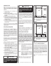
NOTE: DIAGRAMS & ILLUSTRATIONS ARE NOT TO SCALE.
9
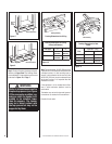
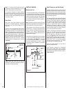
Step 4. Note: Chimney sections are con-
structed with a unique locking tab
design, which ensures an immediate,
tight assembly between sections. Plan
your chimney requirements carefully
before assembly as chimney is diffi cult
to disassemble after installation. If
disassembled, the tabs might become
damaged. Be certain tabs are properly
formed to ensure locking tabs engage
properly.
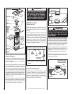
The Security Chimneys FTF8 chimney system
is a two piece chimney, which snap together
from the fi replace up. Start with the inner fl ue
section with the lanced end up, snap lock it in
to the matching collar on top of the fi replace.
At all subsequent joints, the upper fl ue section
fi ts into the preceding fl ue section. Each piece
snaps together by means of locking tabs (9
locking tabs per joint). Check each piece by
pulling up slightly from the top to ensure proper
engagement before installing the next section.
If the fl ue has been installed correctly, it will not
separate when you test it. Also, the inner fl ue
joint where each section is joined should be
tight and fl at without gaps (Figure 19).
Note: Assemble one component of chimney
at a time (inner section fi rst, then outer section
last) before proceeding with the next complete
section.
Continue to assemble the chimney up through
framed opening. Assemble just enough to
penetrate the roof fl ashing openings (Figure
21). Maintain 1" minimum air space to insula-
tion and building materials and always check
each chimney joint (inner and outer) to ensure
proper engagement. Check vertical alignment
of chimney so that it projects from the roof in
true vertical position.
Security's chimney sections do not need to be
screwed together. Additional reinforcement is
not necessary except in certain offset conditions
(refer to Page 13, Figure 35).
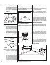
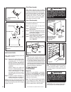
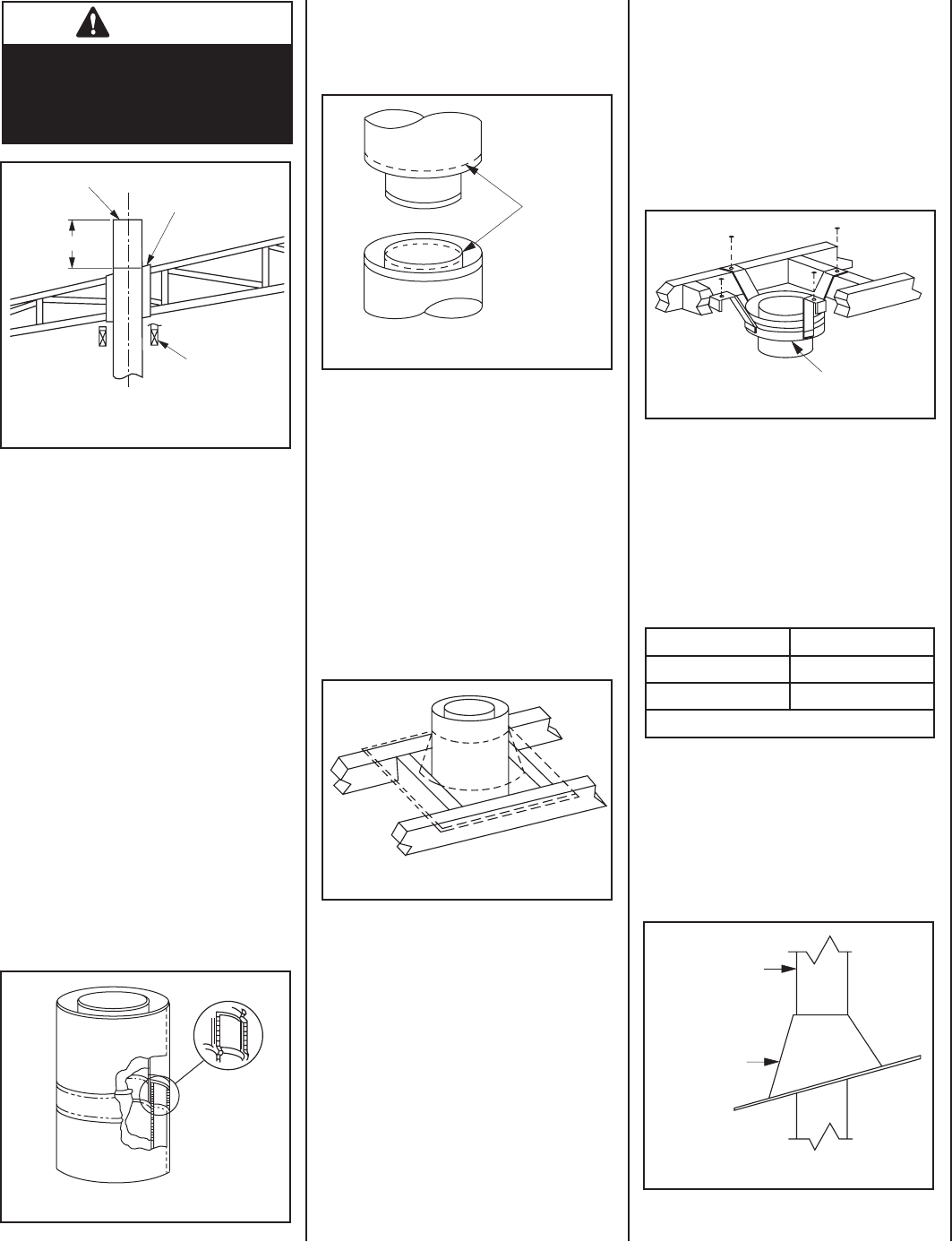
Step 5. The height of vertical chimney pipe sup-
ported only by the fi replace must not
exceed 30'. Chimney heights above 30'
must be supported by a Model FTF8-S4
stabilizer installed at 30' intervals.
Note: The Model FTF8-S4 adds 3" net effective
height to the total chimney system.
Install the Model FTF8-S4 stabilizer by fi tting
inner section down into respective section of
proceeding fl ue pipe and locking outer stabilizer
section into place over the outer chimney pipe.
Position for proper clearance through framed
opening and nail straps securely (under tension
in “shear”) into place on framing. Use 8d nails.
Attach successive lengths of chimney pipe
directly to stabilizer using same techniques as
described in Step 4 (Figure 22).
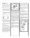
Next, slide roof fl ashing over extended chimney
section that previously has been installed above
the roof opening in Step 4. Slide fl ashing all the
way down until the fl ashing base rests fl at on
the roof (Figure 23). Again, check the vertical
position of the chimney and the minimum air
space to combustibles.
Note: Do not apply excessive pressure to any
subsequent chimney sections following the
stabilizer when installing. Ensure each subse-
quent chimney section is securely attached by
testing as noted in Step 4.
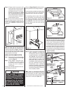
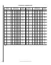
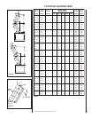
Step 6. Select the proper Security Chimneys
roof fl ashing based on pitch of roof.
Use chart below for selection:
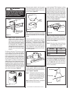
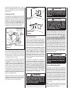
WARNING
Do not allow insulating materials to
be blown into the space inside the
thimble and the chimney. To do so
could result in a fi re hazard.
Thimble Cathedral
Ceiling
14" Min.
Outer Pipe Of
Chimney
Use Adjustable Thimble
FM8-AT1 For All Ceiling
Piches, From Flat To
3/12 Pitch.
Figure 18
Figure 22
FTF8-S4 Stabilizer
Roof Pitch FTF8
Flat to 6/12 F8-F6
6/12 to 12/12 F8-F12
Table 2
FTF8 Chimney
FTF8 Flashing
Figure 23
Figure 21
Figure 19
Outer pipe section installs in just the opposite
way; the lanced end goes down and each new
section goes OVER the outside of the previous
section installed (Figure 20).
Figure 20
Locking
Tabs
(Lances)