


NOTE: DIAGRAMS & ILLUSTRATIONS ARE NOT TO SCALE.
14
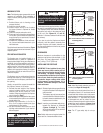
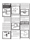
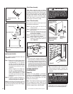
Offset Elbow Assembly
Offset elbows install the same as chimney
sections. First, snap the inner section INTO the
preceding inner section of fl ue. Check connec-
tion by pulling up slightly to ensure a tight fi t.
Next, the outer sections snap lock OVER the
preceding outer section of chimney. Again,
check outer section by pulling up slightly to
ensure proper connection is made.
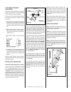
Return Elbow Assembly
Return elbows install the same way as round
terminations and stabilizers:
Step 1. Hold return elbow over top of last
chimney section.
Step 2. Center inner slip section into inner fl ue
pipe-slip down.
Step 3. Center outer-locking section over outer
chimney pipe. Push down until locking
joint has fi rmly engaged.
Step 4. Pull up slightly on return elbow to ensure
locking joint has fi rmly engaged.
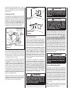
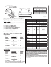
Step 5. Secure support straps to framing
members by nailing under tension in
sheer (Figure 35).
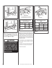
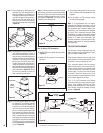
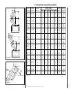
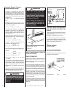
INSTALLING OFFSETS
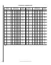
First, review the Offset Elevation Chart and
Figure 34 for reference.
Step 1. Determine the offset distance where
chimney is to pass through the fi rst
ceiling-dimension “A.” To fi nd this
point on your ceiling, fi rst determine
the center point for a vertical chimney
following the instructions for vertical
installation.
Measure height to the ceiling from
the top of fi replace-dimension “B.”
Use the appropriate Offset Elevation
Chart to fi nd dimension “A.” Mark
point where you will drive your nail to
show the center point for your offset
ceiling cut.
Step 2. Proceed by using the Straight Up In-
stallation Instructions for cutting and
framing ceiling and roof openings.
Note: See Framing and Dimension Chart for
the sizes of the ceiling and roof openings. The
size of the roof opening varies with the degree
of pitch of the roof.
Notes:
• The return elbow assembly performs the
same function as a stabilizer. Consider this
when determining the need for a stabilizer.
• Do not apply excessive pressure to any
subsequent chimney section following return
elbow assembly when installing. Ensure that
each subsequent chimney section is securely
attached by testing as noted above.
OPTIONAL EQUIPMENT
CONSIDERATIONS
Blower Kit
A Blower Kit model BFK36 is preinstalled,
standard, on model BCD36MH and is available
as an option for model BC36MH. The optional
Blower Kit can be installed prior to or after
installation of the fi replace.
Note: These fi replace models are not supplied
with an optional wall switch (FWSK) for fan
operation. BFK36 blower kits may be operated
with their integral blower (On/Off) switch.
Note: The utilization of fans will increase the
air fl ow around the fi rebox. However, only
a minimal increase in heat output should be
anticipated.
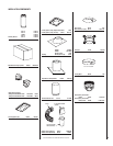
Underside Of Chimney
Figure 33
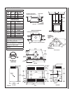
Figure 34
Chimney Section (S)
FTF8-E30 Return Elbow*
FTF8-30 Offset Elbow*
B
A
*Part of Offset/Return Package Model FTF8-ES30
Figure 35
Return
Elbow
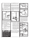
Figure 36
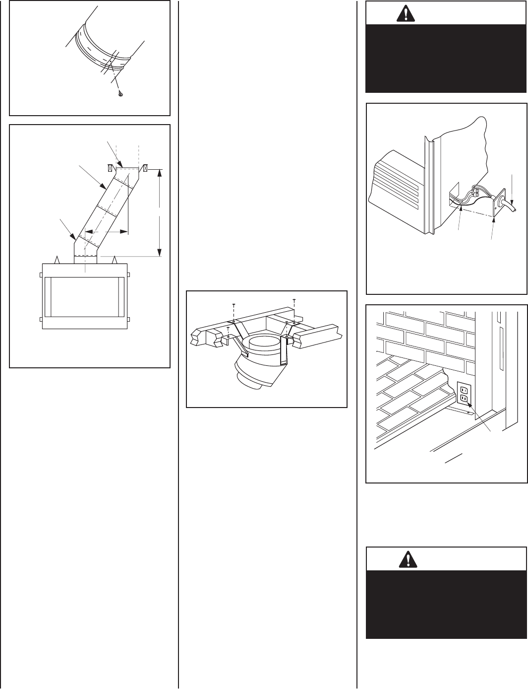
Figure 37
HOUSE
WIRING
COVER PLATE
Replace Cover Plate
After Electrical
Hook-Up
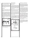
POWER TO THE FIREPLACE
The Optional Blower Kit
Operates on 115 volt 60 Hz
150 watts AC
GROUND
WIRE
House Wiring Must Be Secured
With The Appropriate Electrical
Connector To The Fireplace
Convenience Outlet Wiring
BLOWER THREE
PRONGED PLUG TO
GROUNDED OUTLET
IMPORTANT
The fi replace must be wired to
the house electrical system at the
time of installation in order for
the fans to operate, (See Figures
36 and 37).
The BFK36 Blower Kit is design certifi ed by War-
nock Hersey for use with these appliances.
IMPORTANT
This fi replace is not intended
to be used as a substitute for a
furnace to heat an entire home.
Use for supplementary heating
only.