


NOTE: DIAGRAMS & ILLUSTRATIONS ARE NOT TO SCALE.
8
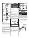
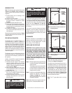
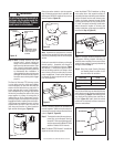
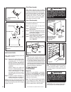
Step 4. Fireplace should be secured to side
framing members using the full length
nailing tabs at the top and bottom of
the fi replace front face. Use screws,
8d nails or equivalent fasteners (Figure
13). This manufactured home model is
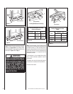
also provided with fl oor brackets used
to secure the fi replace to the fl oor to
prevent shifting in transit.
Note: The use of fl oor brackets are optional.
They are included (unbent) inside the Com-
bustion Air Kit package, located inside the
fi rebox. Refer to Figure 8 for suggested bracket
placement.
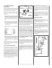
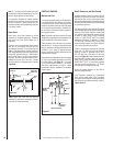
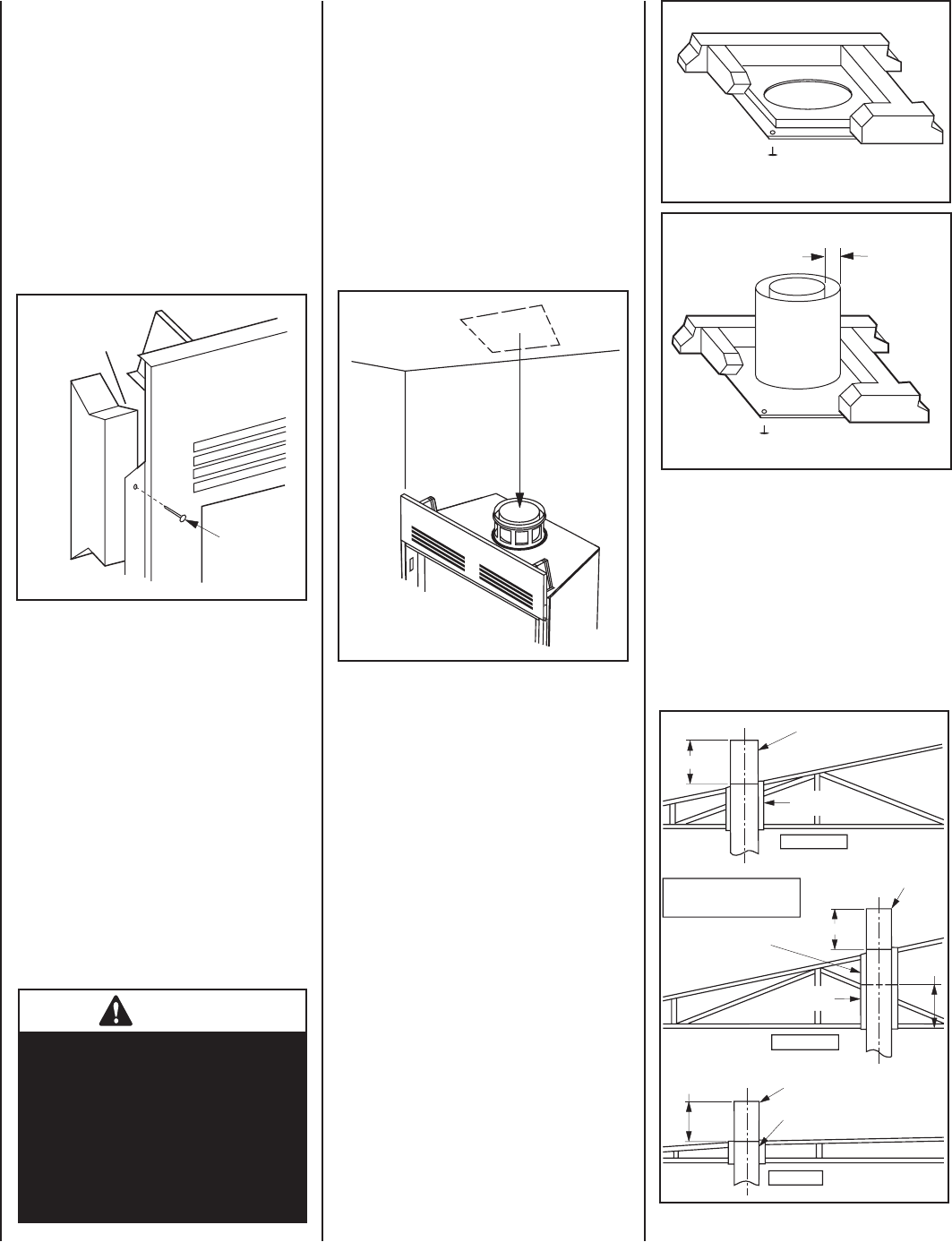
Ensure the thimble penetrates the roof opening.
The thimble must extend completely through the
ceiling or roof cavity to the outermost plane of
the roof. Note: Thimble extensions (F8-TE26)
are available from your dealer for constructions
in which the distance between the outside of the
roof and the inside of the ceiling exceeds 13".
The thimbles and their extensions provide for
zero clearances to combustibles and must be
used at the ceiling/roof in manufactured homes
(Figures 17 and 18).
Note: The nailing tabs and the area directly
behind the nailing tabs are exempt from the
clearances described on Page 5. Maintain at
least 1/2" clearance from the fi rebox wrapper
to the framing at the closest point of contact,
directly adjacent to the fl ange.
INSTALLING THE CHIMNEY SYSTEM
Step 1. Before continuing, check the operation
of the damper, as described on Page
4, (refer to Figure 2).
Step 2. Using standard construction fram-
ing techniques, construct opening
for chimney route up through the
ceiling(s) and roof or through an
outside chase.
Framing must maintain adequate minimum air
space clearance at all times.
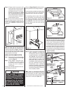
Step 3. Position appropriate thimble/fi restop
spacer combination at ceiling and
nail temporarily with two (2) 8d nails
or equivalent fasteners (see Figures
16, 17 and 18). Use one fastener on
opposite sides to hold thimble/fi restop
spacer combination in position. Nail
permanently, using at least two (2)
more fasteners, after chimney sections
have been assembled through the
thimble/fi restop spacer combination
and after any necessary adjustments
have been made. Firestop spacer must
be secured by at least four (4) fasteners
when completely installed.
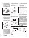
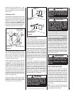
Note: If there is a room above ceiling level,
fi restop spacer must be installed on the bottom
side of the ceiling. If an attic is above ceiling
level, fi restop thimble must be installed on the
bottom side of ceiling joist (Figure 15).
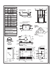
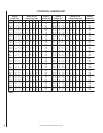
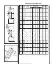
Reference Figures 10 and 11 and their charts for
framing dimensions at Ceilings and Roofs.
In new construction, to determine chimney center
line, use plumb line from roof or ceiling above
fi replace to center of fl ue collar on fi replace.
For remodeling, plumb to center of fl ue collar
from ceiling above, drive nail through ceiling
from below to mark position, then mark and
cut to passage from above ceiling (around
nail) (Figure 14). Then plumb from ceiling or
roof level directly above hole which has just
been completed.
Screw, 8d
Nail Or
Equivalent
Fastener
Figure 13
CAUTION
Allow minimum 1" chimney
air space to framing members
throughout chimney installation.
A minimum 1" air space must be
maintained from all insulation
and building materials extend-
ing for any continuous length
surrounding the chimney.
Figure 14
Firestop Thimble
Attic Above
1”
Clearance
Minimum
Firestop Spacer
F8FS 2
Room Above
Figure 15
Figure 16
Figure 17
Note: Trim Thimble/
Extension To Desired Length
And Pitch At The Rood Line
14" Min.
Pitched Roof
Pitched Roof
Bow Roof
14" Min.
Outer Pipe Of
Chimney
Outer Pipe Of
Chimney
Outer Pipe Of
Chimney
14" Min.
Thimble
FM8-AT1
13"
Thimble
FM8-AT1
Thimble
FM8-AT1
Thimble
Extension
F8-TE26