


NOTE: DIAGRAMS & ILLUSTRATIONS ARE NOT TO SCALE.
15
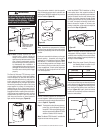
Gas Line Connection
Install a 1/2” gas supply line through fi replace
wall for connection to a decorative gas appliance
inside the fi rebox. Outside, the gas supply line
connects to a gas shut-off valve recessed fl ush
into the wall or fl oor. The valve should be con-
trolled by a removable valve key for safety.
Always plumb gas line installation per local
codes. Check all connections using a gas leak
test solution (also referred to as bubble leak
solution). Note: Using a soapy water solution
(50% dish soap, 50% water) is an effective
leak test solution but it is not recommended,
because the soap residue that is left on the
pipes/fi ttings can result in corrosion over time.
Never test any gas line connection with a match
or open fl ame.
This provision is intended for connection to
a decorative gas appliance incorporating an
automatic shut-off device and complying with
the Standard for Decorative Gas Appliances for
installation in vented fi replaces, ANSI Z21.60
(1991) or American Gas Association draft re-
quirements for Gas-Fired Log Lighters for Wood
Burning Fireplaces, Draft No. 4 dated August,
1993. Install in accordance with the National
Fuel Gas Code, ANSI Z223.1. This complies
with the revised U.L. 127 standard.
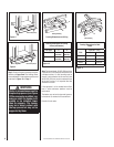
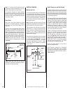
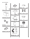
If you’re installing a gas line, connect it before the
fi replace is framed and enclosed in the fi nished
wall. The gas knockout is determined by the
indentation located at the bottom and slightly
off center in the side refractories. THE KNOCK-
OUT IS ALWAYS REMOVED FROM INSIDE THE
FIREPLACE. DO NOT REMOVE THE KNOCKOUT
UNLESS YOU ARE INSTALLING A GAS LINE.
If removal is attempted from the outer wrap-
per, side refractory damage may occur. With a
medium-sized hammer, lightly tap the surface of
the indentation. The refractory material is very
thin in this area and is easily removed. Once
a small hole has been made, continue tapping
until you have reached suffi cient diameter for
the gas line to fi t through. The entire knockout
does not have to be removed. Remove insulation
in the gas line channel.
Always check local building codes. Instal-
lation of the BFK36 Blower Kit must comply
with local regulations as well as the National
Electric Code.
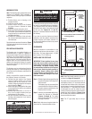
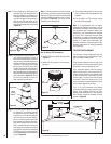
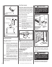
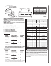
Combustion Air Kits
These appliances are equipped with an outside
(make-up) air door and integral actuator arm and
an outside air kit with a collar, duct and hood
(90L83). The appliance must be installed with
an outside air vent system (Figure 38). These
kits come complete with detailed installation
instructions and all components necessary in
completing a combustion air vent system.
Figure 38
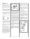
After completing the installation of the com-
bustion air vent system the actuator arm must
be put in service and tested to ensure proper
operation before completing any enclosure
around the fi rebox. Failure to do so may result
in extensive and costly rework.
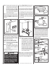
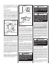
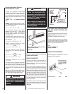
Locate the actuator arm along the right side
of the appliance fi rebox opening and refer
to Figure 39. To operate, push the end of the
actuator to the left as shown in Figure 39, until
it "pops" free of its "locked" position. Pull the
actuator forward to open the combustion air
door, and push it back to close. To "lock" the
combustion air door closed, ensure the actuator
is pushed all the way back then push the end
of the actuators to the right until the step in the
actuator moves behind the appliance front face
within the slotted opening.
Operate the actuator through several cycles
including the "lock position. Ensuring proper
operation and freedom of movement. Return
the actuator arm to the locked position.
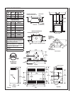
Air Inlet Assembly
(Attach To Floor)
Non-Combustible
Class 0 Or Class 1
6 Inch Air Inlet Duct
Actuator
Arm
Clamp
Securely
At Top And
Bottom
Vented Crawl Space
“Pop” Actuator to
the Left Before
Initial Use
Pull Forward to Open,
Push Back to Close
Combustion Air
Actuator
WARNING
This fi replace has not been tested
with an unvented gas log set. To
reduce risk of fi re or injury, do
not install an unvented gas log
set into this fi replace.
CAUTION
When using the decorative gas
appliance, the fi replace damper
must be set in the fully open
position.
CAUTION
Plumbing connections should
only be performed by a quali-
fi ed, licensed plumber. Main
gas supply must be off when
plumbing gas line to fi replace
or performing service.
IMPORTANT
Repack insulation material in
square hole around gas line,
interior and exterior of fi replace,
to seal.
COLD CLIMATE INSULATION
If you live in a cold climate, it is especially
important to seal all cracks around the fi re-
place and wherever cold air could enter the
room with noncombustible material. Surround
material must be caulked where it meets the
black metal facing of the fi replace to avoid cold
air intrusion. Use noncombustible caulking
material only on fi replace facing to seal. Also,
the outside air inlet duct should be wrapped
with noncombustible insulation to minimize
the formation of condensation. Do not place
insulation materials directly against the chim-
ney sections.
Note: 1" (25 mm) air space must be preserved
for all materials extending for any continuous
length adjacent to the chimney.
Figure 39