


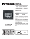
NOTE: DIAGRAMS & ILLUSTRATIONS ARE NOT TO SCALE.
5
ASSEMBLY STEPS
Note: The following steps represent the normal
sequence of installation. Each installation is
unique, however, and might require a different
sequence.
1. Position fi rebox prior to framing or into
prepared framing.
2. Install the chimney system.
3. Connect house wiring to the fireplace
for blower (blower is optional for model
BC36MH).
4. Install the outside combustion air kit.
5. Plumb gas line if a decorative gas appliance
will be used. (Gas connections should only
be performed by an experienced, licensed/
certifi ed tradesman).
6. Complete the installation, fi nish wall mate-
rial, surround and hearth extension to your
individual taste.
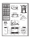
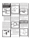
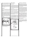
Study the three dimensional illustration (Figure
1) to get a general idea of each element of your
fi replace system.
PRE-INSTALLATION NOTES
The fi replace may be installed directly on a
combustible fl oor or raised on a platform of
an appropriate height. Do not place fi replace on
carpeting, vinyl or other soft fl oor coverings. It
may, however, be placed on fl at wood, plywood,
particle board or other hard surfaces. Be sure
fi replace rests on a solid continuous fl oor or
platform with appropriate framing for support
and so that no cold air can enter the room from
under the fi replace.
The fi replace may be positioned and then the
framing built around it, or the framing may be
constructed and the fi replace positioned into
the opening.
Usually, no special fl oor support is needed for
the fi replace, however, to be certain:
1. Estimate the total weight of the fi replace
system including chimney and surround
materials such as brick, stone, etc., to be
installed. Shipping weights for the fi replace
may be found on Page 7.
2. Measure the square footage of the fl oor space
to be occupied by the system, surrounds and
hearth extensions.
3. Note the fl oor construction, i.e. 2 x 6’s, 2 x
8’s or 2 x 10’s, single or double joists, type
and thickness of fl oor boards.
4. Use this information and consult your local
building code to determine if you need ad-
ditional support.
CAUTION
Do not block the heat-circulating
air inlet and outlet ports. Doing
so may result in a potential fi re
hazard.
CAUTION
The structural integrity of the
manufactured home fl oor, wall,
ceiling and roof must be main-
tained.
The fi restop thimble supplied with the unit must
be used on a manufactured home installation.
The fi restop thimble must extend completely
though the roof cavity to the outermost plane
of the roof (See Figures 16, 17 and 18).
Maintain 1" clearance between the thimble and
the chimney.
If you plan to raise the fi replace and hearth
extension, build the platform assembly then
position fi replace and hearth extension on
top. Secure the platform to the fl oor to prevent
possible shifting.
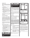
CLEARANCES
Minimum clearance to combustibles for the
appliance is as follows: sides and back - 1" (25
mm), fl oor - 0" (0 mm), adjacent wall - 12" (305
mm), ceiling - 37-1/2" (953 mm).
INSTALLING THE FIREPLACE
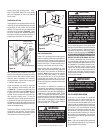
IMPORTANT: Plated polished brass glass
doors may have a plastic covering over all
brass pieces for protection during shipping
and handling. The plastic covering should
be removed after installation of the fi replace
before its use. Under the plastic covering is
a protective lacquer coating which should
not be removed. In some instances, if it is
removed, irreversible damage to the brass
fi nish could occur.
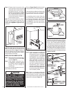
Step 1. Slide the fi replace into prepared framing
or position fi replace in its fi nal position
and frame later.
The fi replace may not be recessed into
a combustible fl oor. Maintain the fl oor
to hearth clearance established by the
fi replace lower front face.
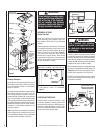
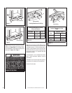
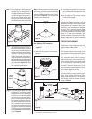
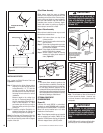
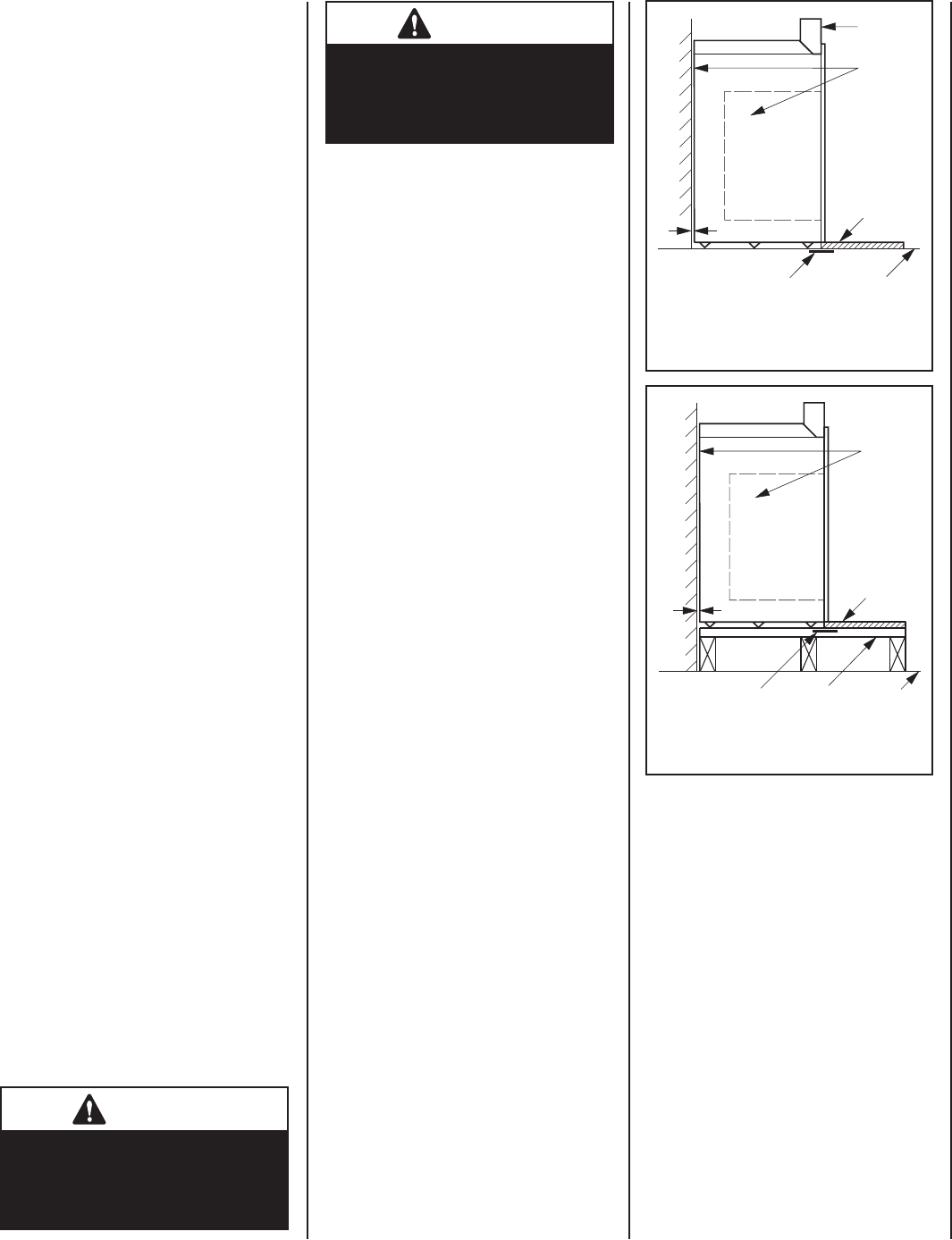
Step 2. Insert the provided metal safety strips,
beneath the fi replace as illustrated
(Figures 6 through 9). The safety
strips should overlap 1/2" for continual
coverage of the fl oor.
Note: Safety strips are not required when fi re-
place rests on a noncombustible surface.
Note: Install the hearth extension only as il-
lustrated (see Pages 16 through 18).
The safety strips should extend from front of
the fi replace at least 1-1/2" and should extend
to be at least fl ush with the sides. In the event a
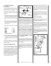
wooden support is used to elevate the fi replace
above the fl oor, a “Z” type safety strip should
be fabricated and used to protect the front
surface of the wood support as well as the fl oor
beneath the hearth extension (Figures 8 and
9). The safety strips should be tacked down to
prevent possible movement.
Note: The “Z” type safety strip is not sup-
plied.
1" (25 mm) Space
Metal Safety Strip Floor
Hearth
Extension
Maintain
1" (25 mm)
Air Space
At Back
And Sides
Top Spacer
Note: Hearth extensions must not interfere with
circulating grillwork
Metal Safety Strip Floor
Hearth
Extension
Platform
1" (25 mm) Space
Maintain
1" (25 mm)
Air Space
At Back
And Sides
Note: Hearth extensions must not interfere with
circulating grillwork
Figure 7
Figure 6