


NOTE: DIAGRAMS & ILLUSTRATIONS ARE NOT TO SCALE.
6
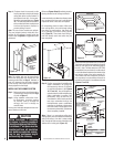
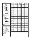
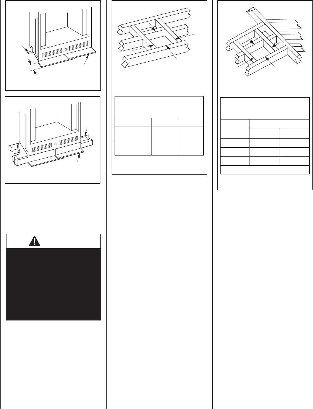
Step 3. Refer to fi replace drawings and speci-
fi cations on Pages 6 and 7 for framing dimen-
sions and details. Frame appliance enclosure as
illustrated in Figure 12 on Page 7.
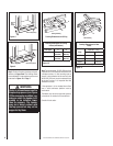
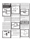
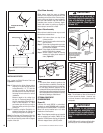
1 ¹⁄₂"
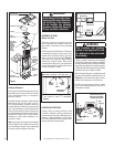
Metal Safety Strips
Optional
Floor
Bracket
Blocking
Metal Safety Strips
Figure 8
Figure 9
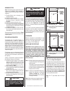
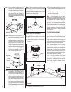
Note: The framed depth, 20-5/8" (524 mm) from
a framed wall, must always be measured from
a fi nished surface. If a wall covering such as
drywall is to be attached to the rear wall, then
the 20-5/8" (524 mm) must be measured from
the drywall surface. It is important that this
dimension be exact.
If the appliance is to be elevated above fl oor
level, a solid continuous platform must be
constructed.
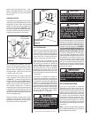
The header may rest on the top metal spacers,
but must not be notched to fi t around them.
Consult all local codes.
WARNING
Under no circumstances can the
fi replace top spacers (see Figure
12) be removed or modifi ed, nor
may you notch the header to fi t
around or be installed lower
than the spacers. The header
may be in direct contact with
the top spacers but may not be
supported by them.
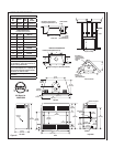
Figure 10
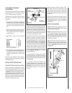
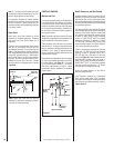
Framing Dimensions for Ceiling
Figure 11
A
B
Ceiling Framing
C
D
Roof Framing
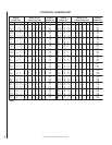
Framing Dimensions for Ceiling
Inches (millimeters)
Flue Type A B
FTF8, Vertical 14-1/2"
(368 mm)
14-1/2"
(368 mm)
FTF8 Offset 30° 14-1/2"
(368 mm)
25"
(635 mm)
Framing Dimensions for Roof
Inches
Pitch
FTF8 at 1" (USA)
CD*
0/12
14-1/2" 14-1/2"
6/12
14-1/2"
17"
12/12
14-1/2"
21-1/2"
* Perpendicular to roof ridge