


NOTE: DIAGRAMS & ILLUSTRATIONS ARE NOT TO SCALE.
11
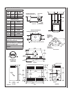
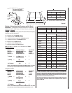
FTF8 CHIMNEY COMPONENT
CALCULATIONS
The minimum installed height of the completed
fi replace system is 10' 6". The maximum height
is 40' 0" when the chimney is exposed.
To determine the number of chimney sections
and chimney components required, follow
these steps:
1. Determine total vertical height of the fi replace
installation. This dimension is the distance
from the surface the fi replace sets on to the
point where smoke exits from the termina-
tion.
2. Determine the number of chimney compo-
nents required, except chimney sections.
This would include thimbles, extensions,
roof fl ashing, etc.
3. The effective heights of the components
are:
The Fireplace = 37”
FTF8-12 = 10-1/4”
FTF8-18 = 16-1/4”
FTF8-24 = 22-1/4”
FTF8-36 = 34-1/4”
FTF8-48 = 46-1/4”
FTF8-CTD Termination = 6”
4 Determine amoun of chimney height required
by subtracting total combined height of all
pre-selected components (fi replace and
chimney components from total desired
height).
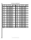
Reference Vertical Elevation Chart and deter-
mine the number of chimney sections (quantity
and length) required.
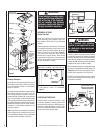
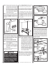
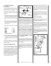
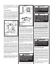
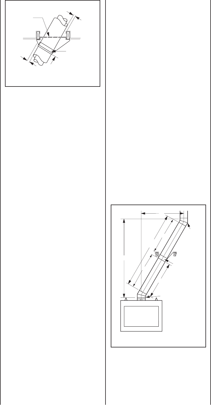
SPECIAL OFFSET INSTRUCTIONS
Chimney 30° Offset through Floor or Ceiling
It may be necessary to assemble the chimney
at 30° when passing through the fl oor or ceiling
area. Use the F8FS30-2 fi restop spacer as shown
in Figure 29. Support the chimney at fl oor or
ceiling penetration with a FTF8 stabilizer if dis-
tance of chimney below ceiling is 10' or more.
Maintain 1" minimum air space to combustibles
from chimney sections. The chimney must pass
vertically through the attic space.
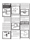
To clear any overhead obstructions, you may
offset your chimney system using Security's 30°
offset and return elbows. Use two elbows - an
offset elbow to initiate the offset and a return
elbow to terminate it. A 30° offset elbow, angling
in any direction, may be the fi rst component used
off the top of the fi replace fl ue collar.
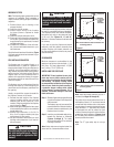
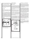
The offset and return elbows may be attached
together, or a section or sections of chimney
may be used between, but do not exceed 20' in
total length between elbows. If sections of pipe
exceed 10' between elbows, a chimney stabilizer
must be used at the midpoint (see Figure 30).
The stabilizer support straps must be attached
under tension (in shear) to structural framing
members above. When two sets of elbows
are used, the maximum combined length of
chimney used between elbows cannot exceed
20' (see Figure 31). Example: If C
1
= 10' then
C
2
cannot exceed 10'.
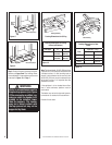
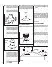
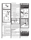
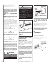
If an offset exceeds 6' in length, each chimney
joint beyond the fi rst 6' of offset to the return
elbow, must be secured by a No. 8 x 1/2" sheet
metal screw located at the underside of the joint
(see Figure 33).
A 1/8" diameter hole must be drilled in the
chimney joint using a 1/8” diameter drill. Hole
should be drilled in center of joint overlap (see
Figure 33). Be sure to drill only through the
outer chimney casting. Do not puncture the
inner fl ue.
Maximum offset of chimney system is 30°.
Two offsets must not be assembled to form
a 60° offset. However, two sets of offset and
return elbows may be used on a single fl ue
system, provided the total height of the system
exceeds 25'.
Return elbow support straps must be securely
attached under tension (in shear) to structural
framing members above. Do not substitute a
FTF8-30 offset elbow in place of a FTF8-E30
return elbow.
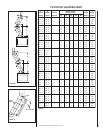
OFFSET CALCULATIONS
Step 1. Use Offset Chart to determine amount of
horizontal offset (A) and height (B) for various
chimney section assemblies.
Step 2. Use “Height of Chimney Only” column
in The Vertical Elevation Chart to determine
combinations of chimney used above return
elbow to achieve desired heights. Reference
Components Effective Height Chart in vertical
elevation chart section.
Step 3. Use Elevation Chart as job estimator only.
Add necessary fi restop spacers and stabilizers
as required. Firestop spacers must be used as
shown in Figure 29 and stabilizers as shown
in Figure 22.
Stabilizer
A
1
20'
Max.
B
1
10' Max.
Offset
Elbow
Return
Elbow
C
2
C
1
Figure 30
Figure 29
F8FS30
Firestop Spacer
FTF8-S4 Stabilizer
30° Firestop
And Room Above
10'
Max.
Room Above
1" Min.
Air Space
1" Min.
Air Space