


4 –Pump 38-Station Controllers Chapter 3: Installation 14 of 44
Connecting the Control Panel to Vacuum Hoppers
Note: Wire size depends on control voltage, distance, number of vacuum
hoppers, and the number of wires in each raceway. Consult a qualified
electrician.
1. On 24 VDC control voltage systems, run a common +24 VDC wire and a
common 0 (zero) VDC wire from the controller to each vacuum hopper in the
system.
2. Run two wires to each vacuum hopper: one each from the controller to the Bin-
Full switch (LS) and to the Atmospheric/Sequence-T solenoid (SOL) valve.
3. Make sure that the solenoid and the proximity switch (if supplied) on vacuum
hoppers are the same voltage (24 VDC) as the control panel voltage. Consult
the control panel serial tag and the solenoid valve nameplates.
4. Properly ground each hopper to reduce static build up generated by material
conveying.
Connecting the Control Panel to the Pump Package
1. Wire the pump package motor starter coil (M) to the terminal provided in the
control panel enclosure.
2. Wire the pump package vacuum relief valve solenoid (SOL A) to the terminal
provided in the control panel enclosure.
3. Wire the pump package vacuum switch (VS) to the terminal located in the
control panel enclosure.
4. On 24 VDC control voltage systems, run a common +24 VDC wire and a
common 0 (zero) VDC wire from the controller to each pump package in the
system.
3-4 Setup
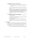
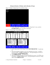
This section provides the procedures for configuring your 4-pump, 38-station controller.
Configuration of your controller includes setting the number of stations and pumps,
setting variables such as convey time and blow-back interval, and setting up passwords.
We recommend that you carry out these procedures in the order given here.
Note: Before carrying out these procedures, install all equipment as described
in this section and in the manual SPD/SPC Series Conveying Systems.