


65
13. SPECIAL PRECAUTIONS WHEN SERVICING THE UNIT
Important!
For your personal safety, be sure to read and understand the following
precautions before servicing.
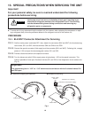
● To avoid risk of injury when servicing the outdoor unit (for instance, when replacing the compressor or repair-
ing a refrigerant leak), follow the procedure below for the refrigerant circuits of the outdoor unit.
PROCEDURE
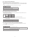
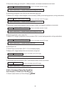
13-1. BLK/WHT Connector Attachment for Servicing
13-1-1. Confirm mains power is switched OFF, then, detach the connectors (BLK and WHT) for the electromag-
netic valves, SV1 and SV2, from the terminals CN4 and CN6 on the PCB.
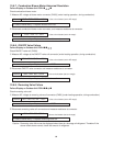
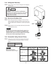
13-1-2. Connect the special connector (field supply) and the connector (BLK and WHT). Following this, re-apply
power at 115V and open the electromagnetic valves, SV1 and SV2.
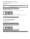
13-1-3. Provide a disconnect switch to the special connector.
13-1-4. Turn the disconnect switch ON to supply power (single-phase, 115V) to the special connector. This
makes it possible to force open 2 solenoid valves (SV1 and SV2) in the refrigeration circuit outdoor unit.
(Fig. 3)
Injuries can occur from burns or inhalation of toxic gas if servicing is per-
formed while refrigerant remains in the refrigeration circuit. This servicing
includes disassembling brazed tubing connections and removing any
refrigeration parts or components.
WARNING
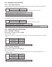
Important!
The procedures given in “13-2” to “13-5” below must be carried out with the 2 solenoid valves SV1
and SV2 open.
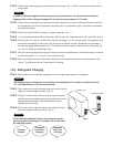
Black
White
CN4
CN6
V2
V1
Outdoor PCB
Power supply
AC115V
Disconnect switch (Field supply)
Special
connector
Connectors for servicing
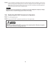
Black
White
CN4
CN6
V2
V1
Outdoor PCB
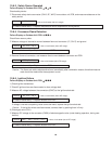
Fig. 1
● Condition at shipping and operation ● Condition at servicing