


60
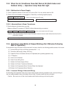
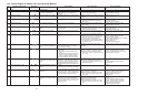
12-6-3. Safety Device Operated
Failure Display on Outdoor Unit PCB: ●● ● ●● ●
Check safety device.
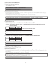
➀ Disconnect safety device connector (CN12, 2P, WHT) from outdoor unit PCB, and measure resistance on the
safety device.
In case of abnormality ➞ Replace temperature fuse or temperature limiting switch.
Normal 1 Ω or less
*Use a circuit tester (set to Ω range).
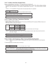
In case of abnormality ➞ Replace outdoor unit PCB.
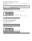
In case of abnormality ➞ Replace outdoor PCB.
➁ Remove flame rod connector, and measure direct current between connector and PCB.
Caution: The flame rod retains electromotive force immediately after combustion ceases, therefore measure-
ment should be made while the equipment is cool.
12-6-4. Erroneous Flame Detection
Failure Display on Outdoor Unit PCB: ●● ● ● ●●
Check flame sensor probe.
➀ Measure voltage of alternative current between flame rod connector (1P, CN17) and ground.
Normal AC 104 – 126 V
Normal DC 1µA or less
*Use a circuit tester (set to AC range).
*Use a circuit tester (set to DC range).
Normal AC 104 – 126 V
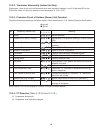
12-6-5. Ignition Failure
Failure Display on Outdoor Unit PCB: ●● ● ● ●
1) Check ignition transformer.
➀ Check if ignition wires are disconnected or have voltage leak.
➁ Measure AC voltage between the connectors (CN07) to the ignition electrode.
In case of abnormality ➞ Replace outdoor unit PCB.
If voltage is normal but sparking noise cannot be heard, replace the ignition electrode.
Caution: If the ignition wires are disconnected, connect them by pushing them in firmly.
2) Check gas valve (GV1).
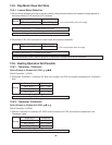
➀ Measure DC voltage at the connector (CN08) of electromagnetic valve (under heating operation, during com-
bustion).
In case of abnormality ➞ Replace outdoor unit PCB.
Normal WHT – WHT DC 90 – 120 V
*Use a circuit tester (set to AC range).
*Use a circuit tester (set to DC range).