


61
Normal ORG – ORG DC 90 – 120 V
Normal WHT – WHT 1 – 2.5 kΩ
Normal ORG – ORG 1 – 2.5 kΩ
In case of abnormality ➞ Replace heating electromagnetic valve.
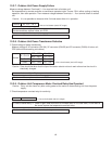
➁ Disconnect heating gas valve (GV1, CN08) connector, and measure resistance at connector.
In case of abnormality ➞ Replace outdoor unit PCB.
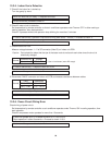
3) Check electromagnetic valve (GV2) of the combination gas valve.
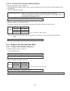
➀ Measure DC voltage at electromagnetic valve connector (CN08) (under heating operation, during combustion).
In case of abnormality ➞ Replace heating electromagnetic valve.
➁ Disconnect heating electromagnetic valve connector (CN08), and measure resistance at connector.
Normal AC 104 – 126 V
In case of abnormality ➞ Replace outdoor unit PCB.
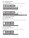
4) Check proportional control valve (PV).
➀ Measure DC voltage at proportional valve connector (CN11) (under heating operation, during combustion).
In case of abnormality ➞ Replace flame rod.
5) Check flame rod.
➀ Check if flame rod connector (CN17, 1P) is connected properly.
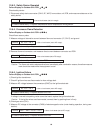
➁ Measure AC voltage between flame rod connector and ground.
*Use a circuit tester (set to Ω range).
*Use a circuit tester (set to Ω range).
Normal BLU – BLU DC 5 – 30 V
*Use a circuit tester (set to DC range).
*Use a circuit tester (set to AC range).
*Use a circuit tester (set to DC range).
In case of abnormality ➞ Replace flame rod.
➂ Disconnect flame rod connector (CN17) and measure direct current at connector.
Normal DC 2µA or more
*Use a circuit tester (set to DC range).
12-6-6. Erroneous Flame-Out Condition
Failure Display on Outdoor Unit PCB: ● ●● ●● ●●
➀ Check in same manner as “Failure Display ●● ● ● ●.”