


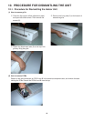
51
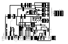
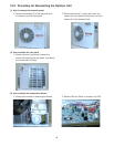
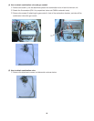
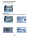
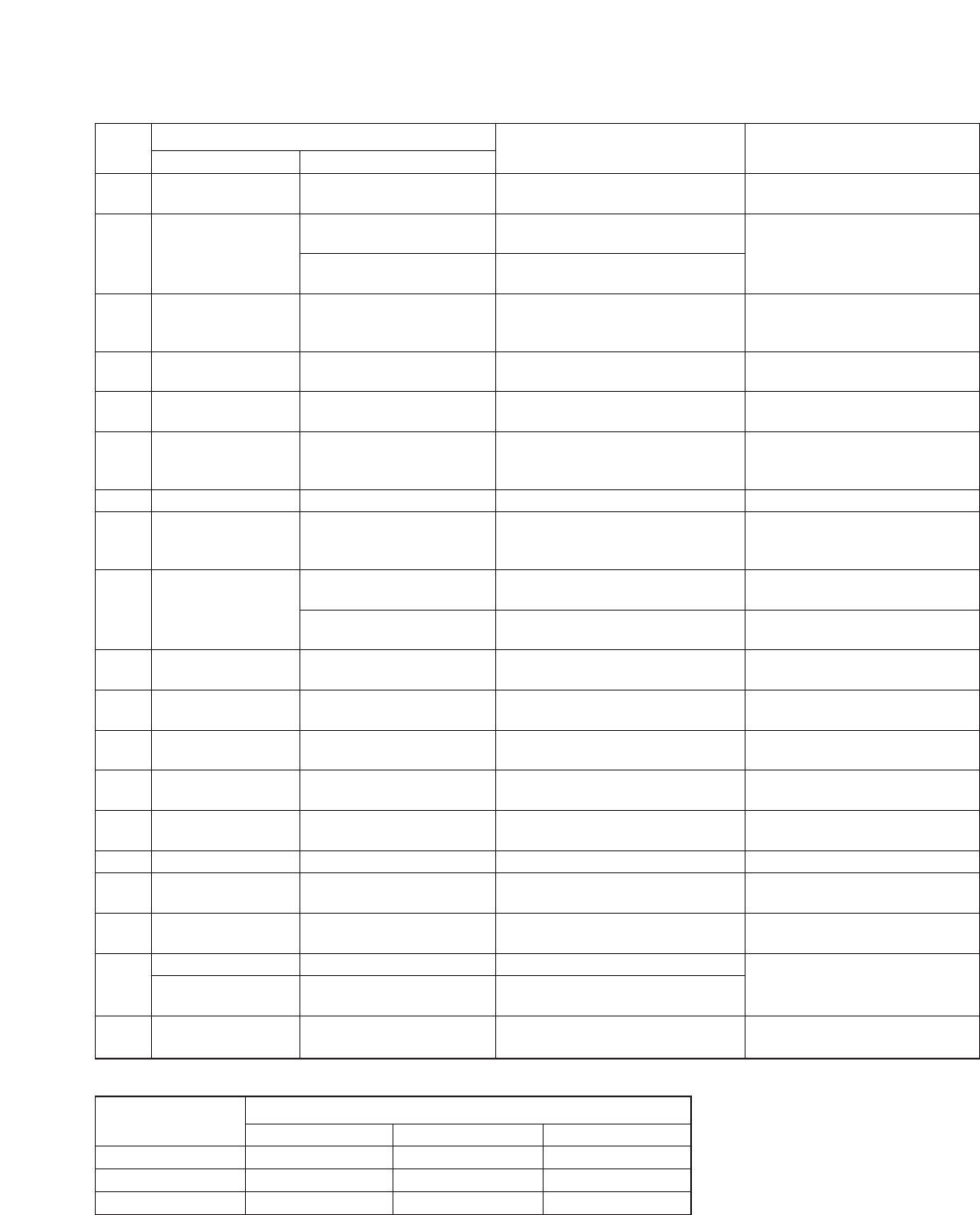
11-3. Checking Electrical Components
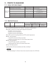
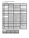
11-3-1. Components
Flow Measurement Target (Normal) Upper: Volt, Amp.
Remarks
No. CO. No. Wire Color (Normal) Lower: Resistance
1 T WHT – BLU
DC 1 – 12 (Pulse)
Flap motor
300 – 450 Ω
BLU – BRN
AC 100 – 130 V
2 S
30 – 60 Ω
Indoor fan motor
RED – BLU
DC 1 – 12V
More than 3000 Pulse/min.
50°F (10°C) 9.0 – 11.0 kΩ
Indoor
3 Z 1WHT – GRY2 68°F (20°C) 5.5 – 7.0 kΩ
86°F (30°C) 3.5 – 4.5 kΩ
room temperature sensor
4 U 3BLK – BLK4
50°F (10°C) 100 – 120 kΩ Indoor
68°F (20°C) 50 – 60 kΩ coil temperature sensor
5 B BLK – BLK
AC 100 – 130 V
Reversing valve
300 – 400 Ω
BLK – WHT
6 R WHT – PNK 1 – 5 Ω Compressor
BLK – PNK
7 Terminal block WHT 3 – 5 A Ampere current
68°F (20°C) 9.8 – 10.8 KΩ
Outdoor
8 KM BLK – BLK 86°F (30°C) 6.8 – 7.3 KΩ
140°F (60°C) 2.4 – 2.6 KΩ
thermistor 1, 2
D PUR – PUR
AC 30 – 115 V
Combustion blower motor
9
10 – 30 Ω
N RED – BLU
DC 1 – 5 V Combustion blower motor
More than 1000 Pulse/min. fan speed sensor
! O BLU – BLU
DC 5 – 24 V Proportional
40 – 160 Ω control valve
" J BLK – Ground
AC 100 – 130 V
Flame sensor probe
More than DC 1 µA
# P YEL – YEL
Not more than DC 1 V Thermal fuse
Not more than 1 Ω bimetal thermostat
$ I WHT – WHT
DC 90 – 120 V
Gas valve 1
1 – 2.5 kΩ
% I ORG – ORG
DC 90 – 120 V
Gas valve 2
1 – 2.5 kΩ
& G RED – RED AC 100 – 130 V Ignition transformer
( E BLK – BLK
AC 100 – 130 V
ON/OFF valve 1
300 – 500 Ω
) F BLK – BLK
AC 100 – 130 V
ON/OFF valve 2
300 – 500 Ω
C WHT – BLU AC 100 – 130 V
~
V
WHT – BRN 70 – 150 Ω Outdoor fan motor
WHT – PNK 300 – 500 Ω
+ W PNK – PNK
Not more than AC 1 V
Overload relay
Not more than 1 Ω
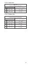
Operation
Outdoor Unit Voltage at Terminal Block
1 – 21– 31– 4
Cooling • Dry 100 – 130 V 100 – 130 V 0 V
Heating 100 – 130 V 100 – 130 V 100 – 130 V
OFF 0 V 100 – 130 V 0 V