


ENVIRONMENTALLY FRIENDLY TECHNOLOGY SUPER ABSORPTION
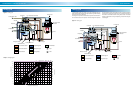
Absorption cooling cycle
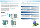
The SANYO super absorption machine applies the same basic absorption
principles but enhances the cycle by adding additional heat exchangers and
a second generator to recover all the available energy of the system and
maximize the unit's COP (see Figure 2).
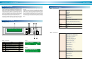
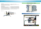
D. High temperature generator section
The diluted solution from the heat exchangers is heated by the burner or
steam upon entering the high temperature generator and separates into re-
frigerant vapor and intermediate solution (see Figure 6).
Line D' to E of Graph 10 shows the heating and concentration process in the
high temperature generator. The diluted solution at point D' is heated at a
Figure 6. High temperature generator
Burner
High temperature generator
Refrigerant vapor
Exhaust gas
Diluted solutionIntermediate solution
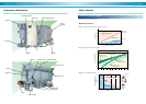
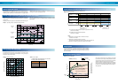
A. Evaporator section
Liquid refrigerant entering the evaporator is dispersed uniformly on the chilled
water evaporator tubes (see Figure 4).
The low pressure of the evaporator causes the refrigerant to be boiled, thus
Chilled water outlet
Chilled water inlet
Absorber
Refrigerant pump
Absorbent pump
Cooling water inlet
Liquid refrigerant
Concentrated solution
Diluted solution
Evaporator
Figure 4. Lower shell
The absorption cycle operates in a vacuum. This permits the liquid refriger-
ant to boil at a lower temperature, transferring the latent heat of evaporation
from the entering chilled water to cooling the chilled water.
Below is a component description of the absorption cycle with reference to
the D¨uhring diagram shown in Graph 10 at page 16.
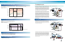
B. Absorber section
Concentrated solution entering the absorber is dispersed uniformly on the
cooling water tubes (see Figure 4). The concentrated solution in the absorber
section absorbs the refrigerant vapor from the evaporator section of the ves-
sel.
Cooling water flowing through the absorber section heat transfer tubes ex-
tracts the heat generated by this absorption process. The concentrated solu-
tion, after absorbing the refrigerant vapor from the evaporator, becomes a
diluted solution.
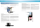
Concentrated
solution
Intermediate
solution
Low temperature
heat exchanger
High temperature
heat exchanger
Diluted solution
Figure 5. Heat exchangers
C. Low and high temperature heat exchangers
The diluted solution, after leaving the absorber section, passes through the
low temperature heat exchanger (see Figure 5) where it is heated by the
concentrated solution. The diluted solution then passes through the high tem-
perature heat exchanger where it is further heated by intermediate solution.
The intermediate and concentrated solutions are cooled by the diluted solu-
vaporizing the refrigerant and causing the latent heat of the vaporized refrig-
erant to cool the chilled water.
Line A to B of Graph 10 describes the process in the absorber. The concen-
tration of the lithium bromide solution entering the absorber section is 63.5%
(all concentration levels and temperatures are approximate). The lithium bro-
mide solution then absorbs the refrigerant vapor from the evaporator section
and is cooled from 50°C to 37°C by the cooling water. This causes the bro-
mide solution to become diluted and it then leaves the absorber at a concen-
tration of 57.7% (point B, Graph 10).
tion. This cooling process of the concentrated solution allows for greater ab-
sorbing power due to its lower temperature.
Line B to C to D' of Graph 10 shows the temperature rise of the diluted
solution in the low and high temperature heat exchangers.
E. Low temperature generator section
The refrigerant vapor from the high temperature generator passes through
the heat transfer tubes of the low temperature generator (see Figure 7). The
intermediate solution from the high temperature heat exchanger passes to
the low temperature generator where it is heated by the refrigerant vapor.
The heated intermediate solution releases additional refrigerant vapor and
becomes concentrated to its final level. The condensed refrigerant in the
heat transfer tubes and the refrigerant vapor of the low temperature genera-
tor section then flows to the condenser.
Line F' to F to G of Graph 10 shows the concentrating process in the low
constant concentration to point D, where the refrigerant vapor is released
and the solution becomes concentrated to 60.8% (point E, Graph 10).
Following the intermediate solution, Line E to F' of Graph 10 shows heat
transfer from the intermediate solution to the diluted solution in the high tem-
perature heat exchanger (see Figure 5).
temperature generator. The intermediate solution enters the low tempera-
ture generator and is heated by the refrigerant vapor from the high tempera-
ture generator. Additional refrigerant vapor is released and the intermediate
solution becomes concentrated into its final concentration level of 63.7%
(point G, Graph 10).
Following the concentrated solution, Line G to A' of Graph 10 shows the
process of temperature reduction in the low temperature heat exchanger by
heat transfer to the diluted solution (Figure 5). Line A' to A shows the tem-
perature reduction of the concentrated solution entering the absorber.