


SUPER ABSORPTIONENVIRONMENTALLY FRIENDLY TECHNOLOGY
1. Work outside the area surrounded by this line
shall be under-
taken at the expense of the owner.
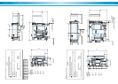
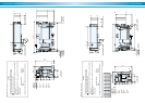
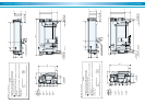
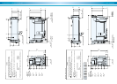
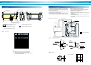
2. Refer to the Dimensions diagrams and specification tables for pipe
connections and diameters.
3. Determine the locations of the chilled, cooling and hot water pump in
due consideration of the pump’s hydrostatic head.
As standard condition, the machine should not be subject to a
pressure larger than 8 kg/cm
2
G. at any water headers.
4. Concerning the temperature control of cooling water, refer to the
section of ”control method of cooling water temperature”.
5. Provide a thermometer and a pressure gauge at the outlet and inlet
of cooling water temperature.
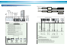
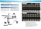
General remarks on piping work
6. Provide an air vent valve in each of the chilled, cooling and hot water
lines at a point higher than the header for chilled, cooling and hot
waters.
7. Lay pipes from the cover of the evaporator, absorber and generator
to drain ditch.
8. Provide a bleeder in the cooling water line for control of water quality.
9. All external water piping are to be provided with JIS 10k welding flanges
by the customer.
10.Be sure to design the location of cooling tower to prevent
contamination of cooling water by exhaust gas from flues.
Supply
Header
Return
Header
Secondary
Chilled
Water pump
Bypass valve
Primary
Chilled water pump
Air
Conditioner
Hot water
Pump
Hot water
3 way valve
Cooling water pump
Cooling
tower
Make up
water
To drain
To drain
F
CC
T
T
T
T
T
P
P
T
P
P
P
P
Air vent
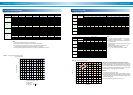
In order to prevent freezing up of chilled water when the chilled water
gets a stop signal, continue the operation of the primary chilled water
pump and secondary chilled water pump and air conditioner during
dilution cycle operation of the chillers.
T
: Thermometer
P
: Pressure gauge
F
: Flow meter
: Water pump : Strainer
: Valve
: Valve
: Thermostat
Tank
above
1m
3
Utility
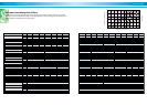
1.Unit selection tables
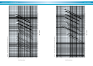
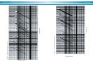
2.Pressure drop curves
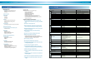
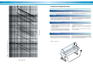
3.Installation and application data
4.Management of cooling water quality
5.Installation examples
Typical piping diagram-laying (LE)
Figure 61. Typical piping diagram