


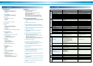
SUPER ABSORPTIONENVIRONMENTALLY FRIENDLY TECHNOLOGY
1. Work outside the area surrounded by this line
shall be under-
taken at the expense of the owner.
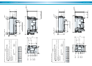
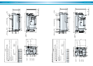
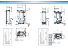
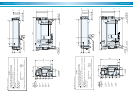
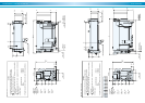
2. Refer to the Dimensions diagrams and specification tables for pipe
connections and diameters.
3. Standard supply steam press. Is 784 kPa (8 kg/cm
2
G). A reducing
valve and safety valve which blows at 981kPa (10 kg/cm
2
G) should
be located near the machine as in above diagram if the supply pres
sure is higher than 784kPa (8 kg/cm
2
G). A pipe should be extended
from this safety valve to release excess steam outdoors.
4. Even if a reducing valve is not required, a strainer, pressure gauge
and drain trap should be provided for each machine near the steam
inlet.
5. The back pressure in the steam drain line should be limited to less
than 49Pa (5 mH2O).
6. Determine the locations of the chilled water pumps and cooling water
pumps in due consideration of the pump’s hydrostatic head.
As standard condition, the machine should not be subject to a
pressure larger than 784kPa (8 kg/cm
2
G) at any water headers.
7. Concerning the temperature control of cooling water, refer to the
section of “control method of cooling water temperature”.
8. Provide a thermometer and pressure gauge at the outlet and inlet of
cooling water and chilled water.
General remarks on piping-laying work
9. Provide an air vent valve in each of the chilled and cooling water lines
at a point higher than the header for chilled water and cooling water.
10.Lay pipes from the cover of the evaporator and absorber to the drain
ditch.
11.Provide a bleeder in the cooling water line for control of water quality.
12.All external water piping with JIS 10k welding flanges are to be
provided by the customer.
13.Be sure to provide a shut-off valve to prevent the steam flow into the
chiller during shut-down.
In case two or more chillers are installed, provide an automatic
shut-off valve.
14.Be sure to design the location of cooling tower to prevent
contamination of cooling water by exhaust gas from flues.
15.Fix the rupture disk on the chiller according to the manual of rupture
disk, if necessary.
16.The chilled and cooling water pumps should preferably be provided
exclusively for each chillers.
17.Provide expansion tank in the chilled water line.
18.There should be a sufficiently large clearance for easy access to the
evaporator, absorber and condenser, to facilitate inspection and
cleaning work.
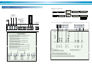
MV
HC
C
By-pass
valve
Supply
header
Return
heater
F
Air conditioner
Chilled water
pump
(primary)
Chilled water pump
(secondary)
Steam
control valve
To boiler
Cooling
water pump
Cooling water
thermostat
Water
supply
Safety valve
Bleeder
valve
Bypass
valve
To drain ditch
Reducing valve
R
Main steam piping
Check valve
T
Tank
about
1m
3
Steam
shutoff
valve
P
T
P
T
P
T
P
P
P
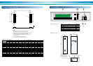
In order to prevent freezing up of chilled water during
diluting operation of chiller, continue the operation of
the chilled water pumps and air conditioner until the
diluting operation is completed.
T
: Thermometer
P
: Pressure gauge
F
: Flow meter
: Water pump : Strainer
: Valve
: Valve
: Thermostat
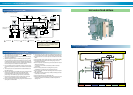
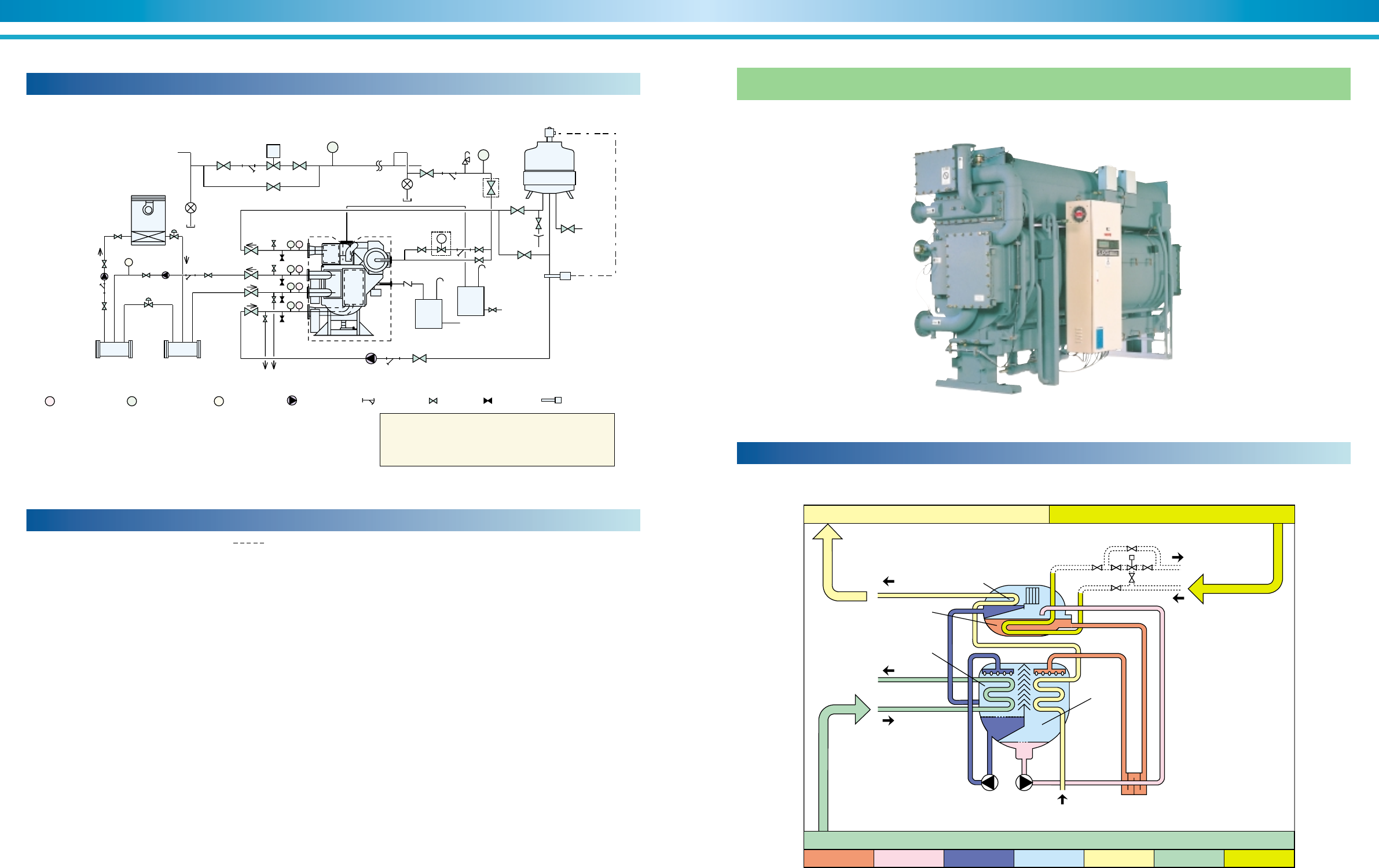
Typical piping diagram-laying (NE)
Figure 48. Typical piping diagram
Cooling cycle schematic
Figure 49. Hot water-fired chillers
Hot water-fired chillers