


SUPER ABSORPTIONENVIRONMENTALLY FRIENDLY TECHNOLOGY
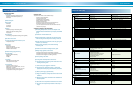
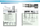
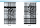
Capacity ratings (DE and NE)
Chilled water temperature Cooling water inlet temperature (°C)
Outlet temp.
5.0
6.0
7.0
8.0
Inlet temp. 28 29 30 31 32 33
8.0
9.0
10.0
11.0
12.0
8.0
9.0
10.0
11.0
12.0
8.0
9.0
10.0
11.0
12.0
8.0
9.0
10.0
11.0
12.0
0.826 0.803 0.780 0.753 0.716 0.634
0.883 0.859 0.834 0.805 0.766 0.678
0.922 0.898 0.871 0.841 0.800 0.708
0.940 0.915 0.888 0.857 0.815 0.721
0.957 0.932 0.904 0.873 0.830 0.735
0.929 0.904 0.877 0.847 0.806 0.713
0.993 0.966 0.938 0.905 0.861 0.762
1.038 1.010 0.980 0.946 0.900 0.797
1.050 1.029 0.999 0.964 0.917 0.812
1.050 1.048 1.017 0.982 0.934 0.827
1.032 1.004 0.975 0.941 0.895 0.792
1.050 1.050 1.042 1.006 0.957 0.847
1.050 1.050 1.050 1.050 1.000 0.885
1.050 1.050 1.050 1.050 1.019 0.902
1.050 1.050 1.050 1.050 1.038 0.919
1.050 1.046 1.016 0.980 0.933 0.825
1.050 1.050 1.050 1.048 0.997 0.883
1.050 1.050 1.050 1.050 1.042 0.922
1.050 1.050 1.050 1.050 1.050 0.940
1.050 1.050 1.050 1.050 1.050 0.957
COW inlet CHW outlet
6.0
7.0
8.0
6.0
7.0
8.0
6.0
7.0
8.0
6.0
7.0
8.0
6.0
7.0
8.0
28.0
29.0
30.0
31.0
32.0
COW inlet CHW outlet
6.0
7.0
8.0
6.0
7.0
8.0
6.0
7.0
8.0
6.0
7.0
8.0
6.0
7.0
8.0
28.0
29.0
30.0
31.0
32.0
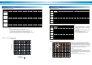
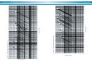
CHW ∆T = 4 deg CHW ∆T = 5 deg
Hot water outlet (°C) Hot water outlet (°C)
CHW ∆T = 6 deg
80.0 81.0 82.0 83.0 84.0 85.0
Hot water outlet (°C)
1.084 1.131 1.177 1.223 1.268 1.300
1.151 1.197 1.243 1.288 1.300 1.300
1.217 1.263 1.300 1.300 1.300 1.300
0.970 1.017 1.065 1.111 1.158 1.204
1.037 1.084 1.131 1.177 1.223 1.268
1.104 1.151 1.197 1.242 1.288 1.300
0.853 0.902 0.950 0.998 1.046 1.092
0.921 0.970 1.017 1.064 1.111 1.158
0.989 1.037 1.084 1.131 1.177 1.223
0.733 0.784 0.834 0.883 0.932 0.980
0.803 0.853 0.902 0.950 0.998 1.045
0.872 0.921 0.970 1.017 1.064 1.111
***
0.661 0.714 0.765 0.815 0.865
0.680 0.733 0.784 0.834 0.883 0.932
0.752 0.803 0.853 0.902 0.950 0.998
80.0 81.0 82.0 83.0 84.0 85.0
1.046 1.092 1.137 1.183 1.228 1.272
1.111 1.156 1.202 1.247 1.291 1.300
1.176 1.221 1.266 1.300 1.300 1.300
0.934 0.980 1.027 1.073 1.119 1.164
0.999 1.046 1.092 1.137 1.182 1.227
1.065 1.111 1.156 1.201 1.246 1.291
0.820 0.868 0.915 0.962 1.008 1.055
0.886 0.934 0.980 1.027 1.073 1.118
0.953 0.999 1.046 1.091 1.137 1.182
0.703 0.753 0.802 0.850 0.897 0.944
0.771 0.820 0.868 0.915 0.962 1.008
0.838 0.886 0.934 0.980 1.027 1.073
0.583 0.635 0.685 0.735 0.784 0.832
0.653 0.703 0.753 0.802 0.850 0.897
0.722 0.771 0.820 0.868 0.915 0.962
80.0 81.0 82.0 83.0 84.0 85.0
1.066 1.112 1.158 1.204 1.249 1.294
1.132 1.178 1.223 1.268 1.300 1.300
1.198 1.243 1.288 1.300 1.300 1.300
0.953 1.000 1.047 1.093 1.139 1.185
1.019 1.066 1.112 1.158 1.204 1.249
1.085 1.132 1.177 1.223 1.268 1.300
0.837 0.886 0.934 0.981 1.028 1.074
0.905 0.953 1.000 1.047 1.093 1.139
0.972 1.019 1.066 1.112 1.158 1.203
0.719 0.769 0.819 0.867 0.915 0.963
0.788 0.837 0.886 0.934 0.981 1.028
0.856 0.905 0.953 1.000 1.047 1.093
0.597 0.649 0.701 0.751 0.801 0.849
0.668 0.719 0.770 0.819 0.867 0.915
0.738 0.788 0.838 0.886 0.934 0.981
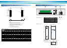
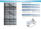
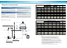
100
90
80
70
60
45678
Supply steam pressure(Kg / cm
2
G)
Selection condition
1) Chilled water 12°C 7°C
2) Cooling water 32°C 37.5°C
Cooling capacity
(%)
XXXX
Note :
1) Cooling water temperature difference : 5.5°C constant
2) The table is used only for the purpose of presuming the capacity factor.
3) In DE model, the proper flow rate of hot water is required in case of heating mode.
It requires proper consumption of hot water for required cooling capacity.
4) Please contact your SANYO representative, if your request is not indicated in the table.
Table 14. Capacity factor (DE and NE)
Capacity ratings (LE)
Table 15. Capacity factor (LE)
Note :
1) Cooling water temperrature difference : 6°C constant
Hot water temperature difference : 5°C constant
2) The table is used only for the purpose of presumpting
the capacity factor.
3) It requires proper consumption of hot water for required
cooling capacity.
4) Please contact your SANYO representative, if your
request is not indicated in the table.
5) ”
***
” mark means out of operation condition.
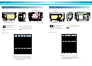
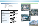
Graph 12. Partial load characteristics
0 102030405060708090100
0
10
20
30
40
70
60
50
110
100
90
80
Load (%)
COP (%)
w/ inverter
w/o inverter
Adoption of the controlling circulation amount of the solution
In order to have a stable and effective operation under the wide range of
hot water temperature given, absorbent pump driven by an inverter con-
trols the optimal operation. This control is that hot water is effectively
utilized to regenerate the refrigerant instead of heating up the solution
not attributed to the cooling capacity at the partial load.
Features;
1. To shorten the start-up period in time.
2. To prevent the excessive heat rejection to the cooling water system.
Even if the heating amount of heat source becomes less, the unit can
operate without fail by means of the procedure that the input is almost
rejected to cooling water.
3.To improve COP at the partial load due to less input.
Graph 11. Cooling capacity and steam pressure
(steam-fired chillers)