


ENVIRONMENTALLY FRIENDLY TECHNOLOGY SUPER ABSORPTION
Sequence of cooling operation (DE)
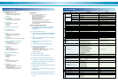
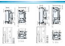
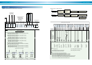
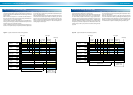
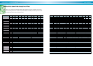
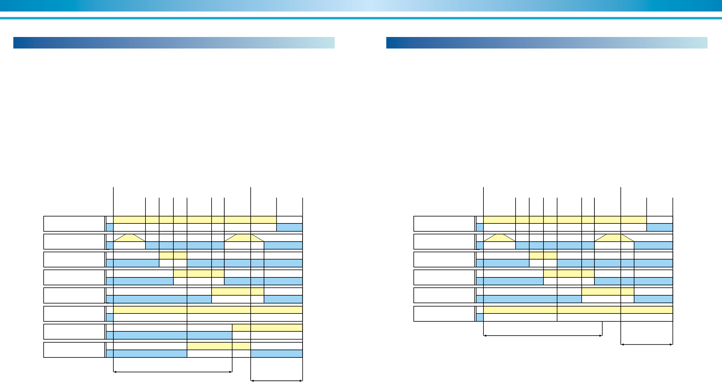
Figure 27 illustrates the typical operating sequence of a SANYO DE di-
rect-fired absorption chiller / heaters. The NE steam-fired unit does not
include the time delays associated with the burner blower, gas valve and
ignition functions.
With a chilled water setpoint of 6.7°C and with the chiller/heaters en-
abled, the start signal will be energized as the leaving chilled water tem-
perature rises to 7.7°C, 1.0°C above setpoint.
The burner initially completes a 36-seconds pre-purge operation that in-
cludes gas valve and supply air damper modulation to full open to insure
complete purging of the combustion chamber.
The No. 1 absorbent pump flow rate is changed during all stages of op-
eration to insure quicker start-up and optimum performance at part load.
As the cooling load is satisfied with the chiller/heaters at minimum load,
the unit will cycle off as the leaving chilled water temperature drops to
5.5°C, 1.5°C below setpoint.
When the microprocessor issues a stop signal, the generator heat source
will shut off and the dilution cycle will start. The dilution cycle will last
between 6 and 15 minutes depending on generator temperature. The
dilution cycle will consist of stopping of the refrigerant pump, absorbent
pump(s), and the cooling water pump in turn. The unit is capable of re-
starting during the dilution cycle.
Figure 27. Typical combustion time chart (cooling operation)
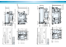
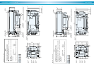
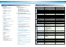
Figure 28 illustrates the typical operating sequence of a SANYO DE di-
rect-fired absorption chiller/heaters in heating mode.
With a hot water setpoint of 55°C, the start signal will be energized as the
leaving heating water temperature drops to 54°C, 1.0°C below setpoint.
The burner initially completes a 36-second pre-purge operation that in-
cludes gas valve and supply air damper modulation to full open to insure
complete purging of the combustion chamber. The No. 1 absorbent pump
flow rate is varied during all stages of operation to insure quicker start-up
and optimum performance at part load. On chiller/heaters with two ab-
sorbent pumps, the No. 2 pump remains off at all times during the heat-
ing mode.
As the heating load is satisfied with the chiller/heaters at minimum load,
the unit will cycle off as the leaving heating water temperature rises to
57°C, 2°C above setpoint.
When the microprocessor receives a stop signal, the generator heat
source will shut off and the dilution cycle will begin. The dilution cycle will
last approximately 5 minutes depending on generator temperature. The
dilution cycle consists of timed stopping of the No. 1 absorbent pump.
The chiller/heaters is capable of restarting during the dilution cycle.
Figure 28. Typical combustion time chart (heating operation)
Sequence of heating operation (DE)
Burner
Blower
ON
OFF
Gas control
valve
Open
Close
Sol. valve
Ignition gas
ON
OFF
No. 2 ABSO
pump
ON
OFF
Ignition ON
OFF
Refrigerant
pump
ON
OFF
Dilution cycle
Approx. 6 -- 15 min.
Approx. 5 min.
Pre-purge
36 sec.
Post-purge
12 sec.
Control
area
Chiller stop
Stop signalStart signal
4
sec.
2
sec.
2
sec.
8
sec.
Sol. valve
Main gas
ON
OFF
No. 1 ABSO
pump
ON
OFF
Burner
Blower
ON
OFF
Gas control
valve
Open
Close
Sol. valve
Ignition gas
ON
OFF
Ignition ON
OFF
Dilution cycle
Approx. 5 min.
Approx. 5 min.
Pre-purge
36 sec.
Post-purge
12 sec.
Control
area
Chiller stop
Stop signalStart signal
4
sec.
2
sec.
2
sec.
8
sec.
Sol. valve
Main gas
ON
OFF
No. 1 ABSO
pump
ON
OFF