


SUPER ABSORPTIONENVIRONMENTALLY FRIENDLY TECHNOLOGY
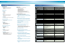
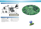
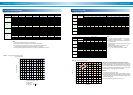
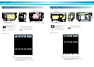
Examples of Installation
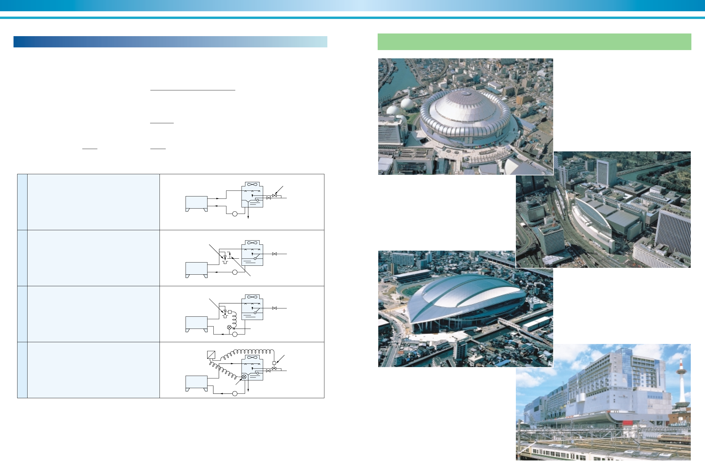
Osaka Dome City User : OSAKA GAS Co.,Ltd. Iwasaki Energy Center
TOKYO INTERNATIONAL FORUM User : Tokyo Heat Supply Co.,ltd
Kitakyusyu Media Dome
Kyoto Station Building
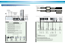
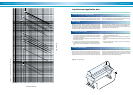
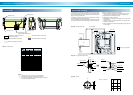
Cooling water blow system
A part of circulating water should be blown to prevent degrading of cooling water quality.
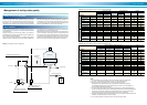
Since concentration ratio is considered about 3 to 4 blowing, water quantity is calculated as follows.
N : Concentration ratio generally N=3
M : Make-up water volume
3,024✕1.85 (exhaust factor)
E : Evaporation loss E=
575 (Latent heat of evaporation at 40°C)
W : Splashing loss generally W=0.2% of circulating water volume
B : Blow volume
E+W+B
M : E+W+B N=
W+B
by the above,
1N
B= • (E+W-NW) M= •E
N-1 N-1
Absorption
chiller
Over flow
Over flow
Blow regulation valve
Solenoid valve
Solenoid valve
Pressure switch
Higher than
cooling water level
Sensor
Water treatment control panel
Make-up
water
Manual valve
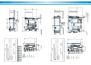
Figure 70.
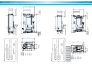
Figure 71.
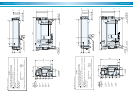
Figure 72.
Figure 73.
Make-up
water
Make-up
water
Make-up
water
Absorption
chiller
Absorption
chiller
Absorption
chiller
P
P
P
P
1
2
3
4
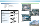
Over Flow
Make-up water is over supplied
by manual valve for over-flow
in cooling tower.
Continuous Flow
Certain amount of circulating
water is blown by blow
regulation valve.
Pressure Switch+Solenoid Valve
Circulation pump is controlled
by pressure switch.
Conductivity Meter+Solenoid Valve
PH Meter+Solenoid Valve
Blow is controlled.