


ENVIRONMENTALLY FRIENDLY TECHNOLOGY SUPER ABSORPTION
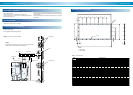
The flue and stack must be heat-insulated and provided with a damper
and a condensate drain.
The flue should never be connected to an incinerator stack.
Locate the top end of the smoke stack at a sufficiently large distance
away from the cooling tower.
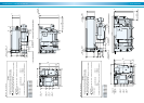
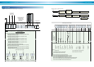
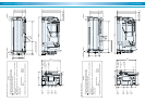
Figure 29. Typical flue and stack installation
Flue & stack connection
If the same stack is used for discharging exhaust from two systems, the
back flow of exhaust should be prevented from going into the one which
is out of operation.
Provide a draft regulator if fluctuations in static pressure are expected
inside the flue.
As illustrated, the steel stack should be lined on the interior surface as a
protection from corrosion due to exhaust gas.
Typical steel stack
Municipal codes in many areas may regulate large capacity chillers con-
suming oil or gas as fuel.
Such regulations should be strictly abided by.
Compliance with local regulation
NOTES :
Please design the draft pressure at flue flange of the chiller/heaters with
negative pressure 0 thru -29.4Pa (0 thru -3mmH2O).
Field supply
Condensate drain
Condensate drain
Internal lining
Stack
Fire-proof mortar
Flue(Insulated)Draft regulator
Damper
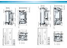
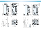
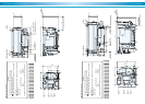
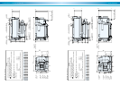
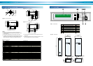
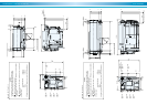
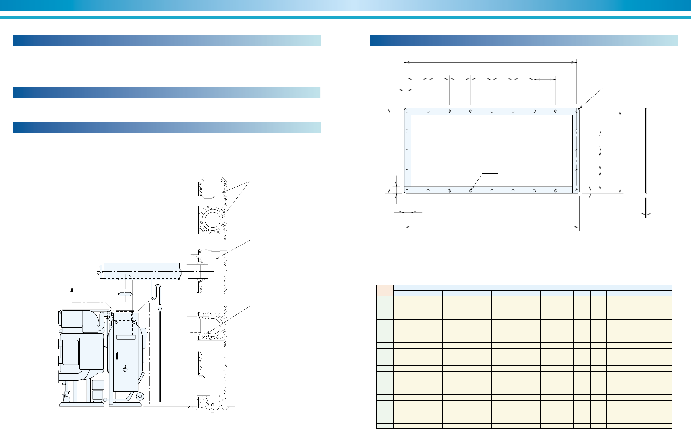
Figure 30. Flue flange
6
A
B
C
D
E F G
H
K
N P
Q
R
A
S
L
M
M
4-R 10
øT hole
NOTE :
1. Field supply
2. Steel material
Model
No.
Dimensions (mm)
15 110 110 110 --- --- --- ---
15 110 110 110 --- --- --- ---
15 110 110 110 --- --- --- ---
15 110 110 110 --- --- --- ---
15 120 120 --- --- --- --- ---
15 120 120 --- --- --- --- ---
15 120 120 --- --- --- --- ---
15 120 120 --- --- --- --- ---
20 100.5 100.5 100.5 --- --- --- ---
20 100.5 100.5 100.5 --- --- --- ---
15 115 115 115 --- --- --- ---
15 115 115 115 --- --- --- ---
15 139.5 139.5 139.5 --- --- --- ---
15 139.5 139.5 139.5 --- --- --- ---
15 139.5 139.5 139.5 --- --- --- ---
15 113 113 113 113 113 --- ---
15 113 113 113 113 113 --- ---
15 113 113 113 113 113 --- ---
15 119 120 120 120 120 120 120
15 119 120 120 120 120 120 120
15 119 120 120 120 120 120 120
15 119 120 120 120 120 120 120
15 119 120 120 120 120 120 120
DE-11
DE-12
DE-13
DE-14
DE-21
DE-22
DE-23
DE-24
DE-31
DE-32
DE-41
DE-42
DE-51
DE-52
DE-53
DE-61
DE-62
DE-63
DE-71
DE-72
DE-73
DE-81
DE-82
ABCDEFGHKLMNPQRST
345 360 38 130 130 --- 275 290 15
345 360 38 130 130 --- 275 290 15
345 360 38 130 130 --- 275 290 15
345 360 38 130 130 --- 275 290 15
375 390 38 120 120 --- 375 390 15
375 390 38 120 120 --- 375 390 15
375 390 38 120 120 --- 375 390 15
375 390 38 120 120 --- 375 390 15
422 442 38 117 118 --- 372 392 15
422 442 38 117 118 --- 372 392 15
475 490 38 120 120 --- 375 390 15
475 490 38 120 120 --- 375 390 15
573 588 38 137 137 -- 426 441 15
573 588 38 137 137 -- 426 441 15
573 588 38 137 137 -- 426 441 15
693 708 38 114.5 114.5 114.5 473 488 15
693 708 38 114.5 114.5 114.5 473 488 15
693 708 38 114.5 114.5 114.5 473 488 15
973 988 38 113 113 112 464 479 19
973 988 38 113 113 112 464 479 19
973 988 38 113 113 112 464 479 19
973 988 38 113 113 112 464 479 19
973 988 38 113 113 112 464 479 19
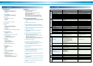
Table 7. Dimensional data
Flue flange dimensional data