


ROBERTS GORDON
®
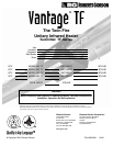
TF-SERIES SUBMITTAL SHEET
© 2004 Roberts-Gordon
APPL ICATION S, ENGINEERING AND DETAI LED GUIDANCE ON SYSTEMS DE SIGN, INSTALLATION AND PRODUCT PERFORMANCE IS AVAILABLE UPON REQUEST. ROBERTS GORDON
®
PRODUCTS ARE TO BE
INSTALLED ONLY IN ACCORDANCE WI TH L OCAL LAWS, CODES AND REGULATIONS, AND ONLY BY A CONT RACT OR QUALIFIED IN THE INSTALLATION AND SERVICE OF GAS-FIRED HEAT ING EQUIPMENT.
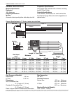
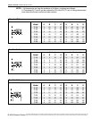
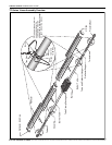
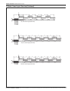
NOTE: 1. All dimensions are from the surfaces of all tubes, couplings and elbows.
2. Clearances B, C and D can be reduced by 50% after 25' (7.5 m) of tubing downstream
from where the burner and burner tube connect.
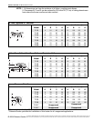
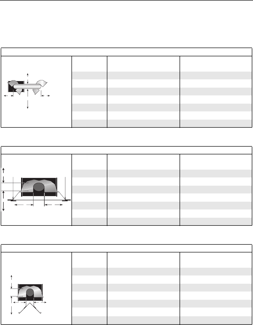
*When installed in the first 20’ (6 m) on each side of the burner.
**Roberts-Gordon prohibits the installation of this heater for all unapproved applications.
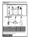
U-Tube, Opposite 45
° Reflector
(inches) (centimeters)
Model ABCDABCD
TF-120 8 54 60 22 21 138 153 56
TF-160 8 60 66 22 21 153 168 56
TF-200 10 64 74 22 26 163 188 56
TF-250 10 70 78 22 26 178 199 56
TF-300 12 74 84 22 31 188 214 56
TF-350 12 76 85 22 31 194 216 56
TF-380 12 76 85 22 31 194 216 56
A
C
D
B
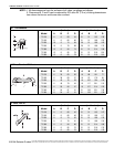
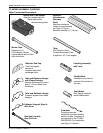
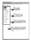
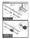
2-Foot Deco Grille, 1-Foot Deco Grille and Protective Grille
(inches) (centimeters)
Model ABCDABCD
TF-120 6 35 63 35 16 89 161 89
TF-160 6 38 66 38 16 97 168 97
TF-200 6 40 71 40 16 102 181 102
TF-250 6 46 77 46 16 117 196 117
TF-300 6 50 80 50 16 127 204 127
TF-350 8 52 82 52 21 133 209 133
TF-380 8 52 82 52 21 133 209 133
A
C
D
B
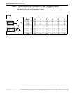
Lower Clearance Shield*
(inches) (centimeters)
Model ABCDABCD
TF-120 6 39 33 39 16 100 84 100
TF-160 6 40 38 40 16 102 97 102
TF-200 6 50 44 50 16 127 112 127
TF-250 6 54 48 54 16 138 122 138
TF-300 6 55 50 55 16 140 127 140
TF-350** Unapproved
Unapproved
TF-380** Unapproved Unapproved
A
C
D
B