


ROBERTS GORDON
®
TF-SERIES SUBMITTAL SHEET
© 2004 Roberts-Gordon
APPLICATIONS, ENGIN EERING AND DETAI LED GUIDANCE ON SYSTEMS DESIGN, INSTALLATION AND PRODUCT PERFORMANCE IS AVAILABLE UPO N REQUEST. ROBERTS GORDON
®
PRODUCTS ARE TO BE
INSTALLED ONLY I N ACCOR DANCE WITH LOCAL LAW S, CODES AND REGULAT IONS, AND ONLY BY A CONTRACTO R QUALIFIED IN THE INST ALLATION AND SERVICE OF GAS-F IRED HEATING EQUIPMEN T.
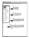
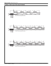
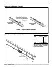
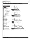
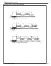
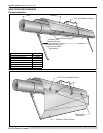
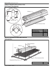
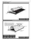
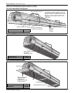
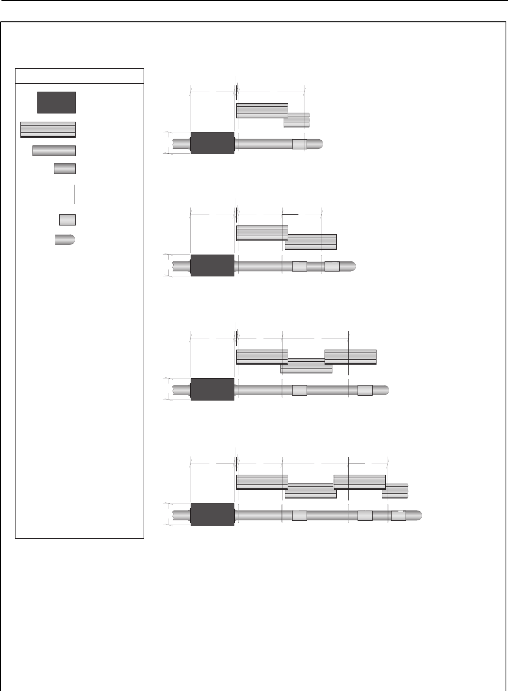
TF-Series U-Tube Layout Overviews
LEGEND
a = 14" (36 cm)
reflector width (not shown)
b = 2" (5 cm)
end cap to burner
c = 2" (5 cm)
end cap to hanger
d = 7'6" (229 cm)
distance first hanger
e = 10' (305 cm)
distance between hangers
f = 5' (153 cm)
distance between last full tube
hanger and half tube hanger
g = 17.5" (44 cm)
burner length
h = 9.5" (24 cm)
burner height
*Requires the last reflector
before the U-Tube to be cut
in half for use on both sides.
**Requires the last tube before
the U-Tube to be cut in half for
use on both sides.
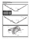
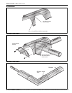
U-Tube
Burner
Reflector
Tube 10' (3m)
Tube/Reflector
Hanger
Coupling
Assembly
Tube 5' (1.5m)**
c
b
de
f
50' (15m) Tube Length* ** (each side)
TF-250
TF-300
TF-350
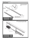
h
g
c
b
de
40' (12m) Tube Length (each side)
TF-200
TF-250
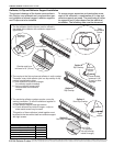
h
g
c
b
d
f
30' (9m) Tube Length**(each side)
TF-160
TF-200
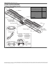
h
g
TF-120
TF-160
c
b
20' (6m) Tube Length* (each side)
e
h
g
U-tube layouts showing one side. Use same measurements for the other side.