


ROBERTS GORDON
®
TF-SERIES SUBMITTAL SHEET
© 2004 Roberts-Gordon
APPL ICATION S, ENGINEERING AND DETAI LED GUIDANCE ON SYSTEMS DE SIGN, INSTALLATION AND PRODUCT PERFORMANCE IS AVAILABLE UPON REQUEST. ROBERTS GORDON
®
PRODUCTS ARE TO BE
INSTALLED ONLY IN ACCORDANCE WI TH L OCAL LAWS, CODES AND REGULATIONS, AND ONLY BY A CONT RACT OR QUALIFIED IN THE INSTALLATION AND SERVICE OF GAS-FIRED HEAT ING EQUIPMENT.
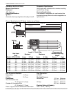
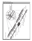
HEATER INSTALLATION
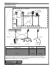
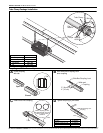
Critical Hanger Placement
Hanger
Side View
Must Be Within 4" (10 cm) Front View
S Hooks
Reflector
Hanger
45° Angle
* Allows for thermal expansion of system
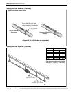
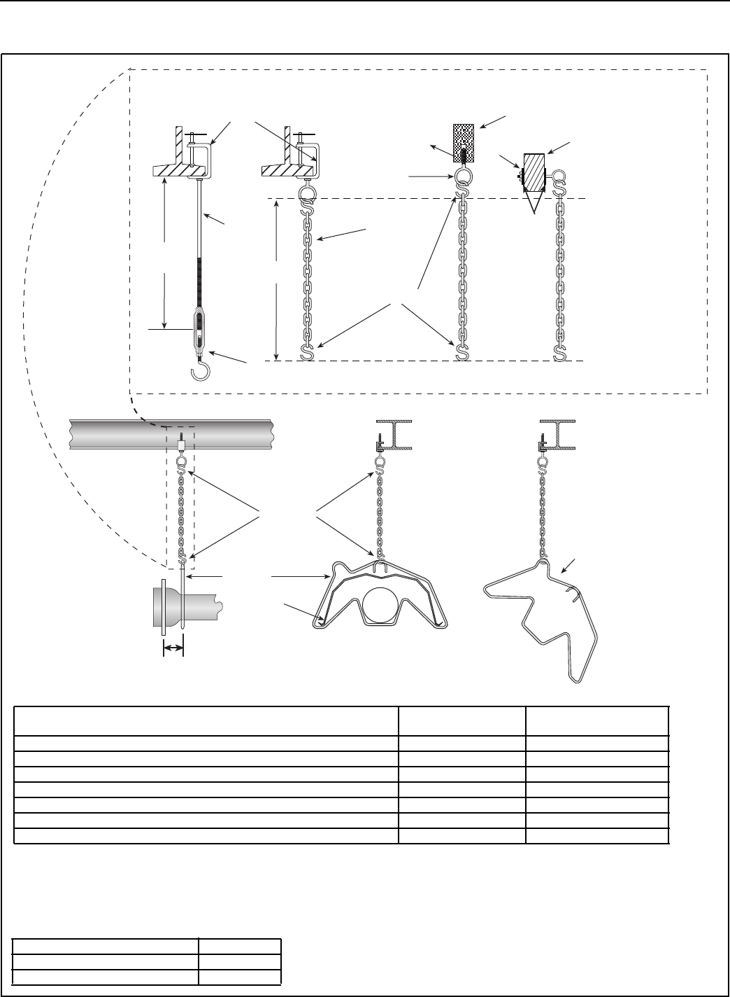
Typical Suspension Details
Rod (3/8")
Beam Clamp
Concrete Beam
Wood Beam
Washers
Locknut
Screw Hook
(3/8")
24" min.*
(61 cm)
X*
Anchor
S Hooks
Chain size
3/16" minimum
Turnbuckle
Not Included
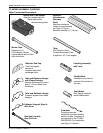
Description Part Number
S-Hook 91907302
Tube/Reflector Hanger 03090100
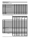
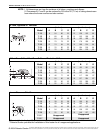
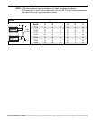
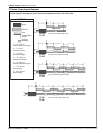
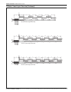
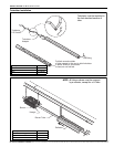
Total Straight Length (both sides) or Length from U-Tube to U-Tube
in a Double "U" Layout
Typical Expansion
Each Side
Minimum “X” Length
0’ - 50’ ±1” (3 cm) 12” (31 cm)
51’ - 60’ ±2” (5 cm) 18” (46 cm)
61’ - 80’ ±3” (8 cm) 24” (61 cm)
81’ - 100’ ±4” (10 cm) 30" (76 cm)
101’ - 120’ ±5” (13 cm) 36" (91 cm)
121’ - 140’ ±6” (15 cm) 42" (107 cm)
141’ - 160’ ±7” (18 cm) 48" (122 cm)
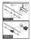
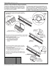
If the installation requires a shorter suspension length than the minimum listed, the suspension
length may be reduced by 6" (16 cm). In this case tube clamps MUST be used at the two farthest
hangers on each side of the burner. See Page 8, Figure .