


ROBERTS GORDON
®
TF-SERIES SUBMITTAL SHEET
© 2004 Roberts-Gordon
APPL ICATION S, ENGINEERING AND DETAI LED GUIDANCE ON SYSTEMS DE SIGN, INSTALLATION AND PRODUCT PERFORMANCE IS AVAILABLE UPON REQUEST. ROBERTS GORDON
®
PRODUCTS ARE TO BE
INSTALLED ONLY IN ACCORDANCE WI TH L OCAL LAWS, CODES AND REGULATIONS, AND ONLY BY A CONT RACT OR QUALIFIED IN THE INSTALLATION AND SERVICE OF GAS-FIRED HEAT ING EQUIPMENT.
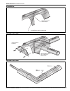
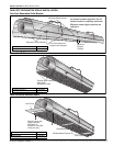
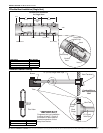
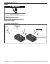
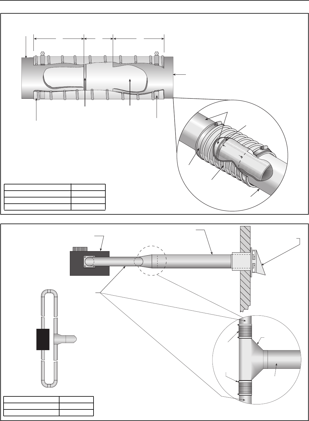
CFlexible Boot Installation (Single Vent)
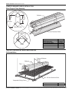
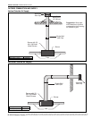
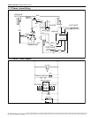
Common Sidewall Venting
Tube
Vent
Boot Clamp
Flexible Boot
Vent Sleeve
Bead
3"
(8 cm)
3"
(8 cm)
2"
(5 cm)
Expansion
Gap
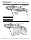
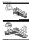
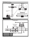
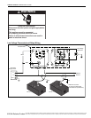
Flexible Boot Installation
for Single Vent
Boot Clamp
Single Wall
Vent Pipe
Flexible
Boot
Tube
Bead
2 min.
(5 cm)
Description Part Number
Rolled Sleeve 09080000
Flexible Boot 4" (10 cm) 91412800
Boot Clamp 4" (10 cm) 91901300
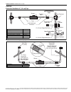
Burner
Tube
Vent Terminal
Combustible or
Non-Combustible
Wall
6" (15 cm) Single Wall Pipe
Flexible
Boot*
6" (15 cm)
Vent Pipe
Vent Tee
Boot
Clamp
* IMPORTANT
Compress boot on installation
to allow at least 2" (5 cm) of
movement on each side for
thermal expansion of tube
away from the tee.
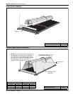
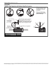
Plan View
Description Part Number
Vent Tee 91916100
Vent Terminal 6" (15 cm) 90502101