


ROBERTS GORDON
®
TF-SERIES SUBMITTAL SHEET
© 2004 Roberts-Gordon
APPL ICATION S, ENGINEERING AND DETAI LED GUIDANCE ON SYSTEMS DE SIGN, INSTALLATION AND PRODUCT PERFORMANCE IS AVAILABLE UPON REQUEST. ROBERTS GORDON
®
PRODUCTS ARE TO BE
INSTALLED ONLY IN ACCORDANCE WI TH L OCAL LAWS, CODES AND REGULATIONS, AND ONLY BY A CONT RACT OR QUALIFIED IN THE INSTALLATION AND SERVICE OF GAS-FIRED HEAT ING EQUIPMENT.
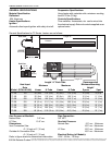
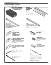
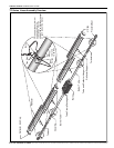
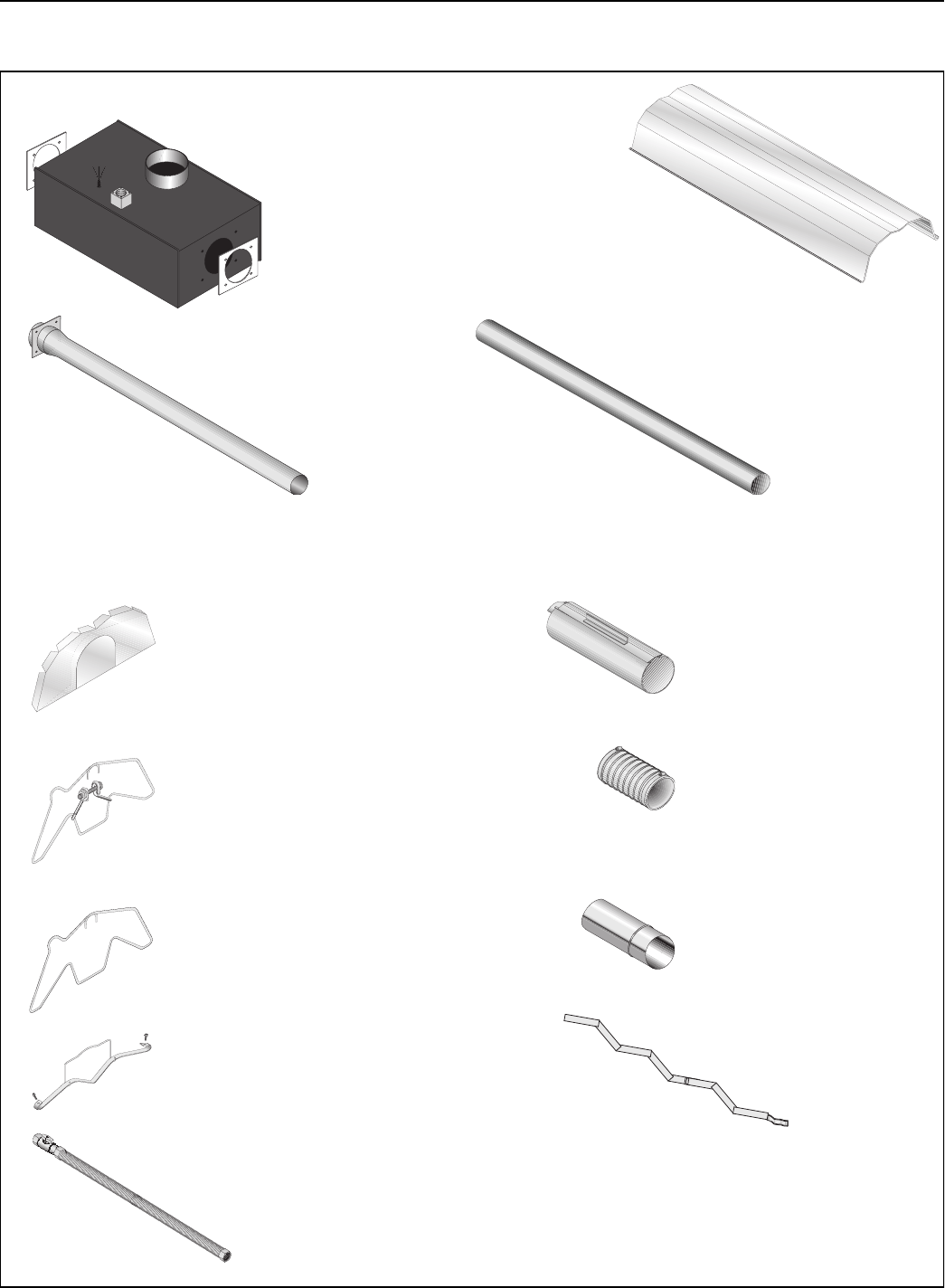
TF-SERIES ASSEMBLY OVERVIEW
Major Component Descriptions
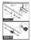
Burner with Tube Gasket
Must be installed with the
flame observation
window facing down.
Reflector
(Aluminum or
Stainless
Steel)
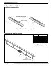
Alternate overlap as
shown on overview and
on Page 10, Figure .
Minimum overlap is 7” (18 cm).
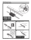
Tube and Reflector Hanger
with Clamp Package
Position this hanger no more
than 4” (10 cm) away from
the burner.
Coupling Assembly
with Lock
Reflector End Cap
Punch out center
section to
accommodate heat
exchanger tube.
Tube and Reflector Hanger
Suspend system from these
hangers.
Flex Gas Line with
Shut Off Cock
Tube
Hot Rolled or Heat
Treated Aluminized Tube
Supplied in 10’ (3 m) lengths.
Burner Tube
Supplied in 10
'
(3 m) lengths. Burner
tube is always the first tube
after the burner.
Reflector Support Strap &
Wire Form
Turbulator
Turbulator must be
installed in the last standard
section of tube. Turbulator is
not required on the TF-250/
300/350/380. For installation
see Page 15, Section .
Flexible Boot
Flexible boot is used to
connect the last tube to
the vent.
Vent Sleeve
Vent Sleeve installed
inside flexible boot.