


ROBERTS GORDON
®
TF-SERIES SUBMITTAL SHEET
© 2004 Roberts-Gordon
APPLICATIONS, ENGIN EERING AND DETAI LED GUIDANCE ON SYSTEMS DESIGN, INSTALLATION AND PRODUCT PERFORMANCE IS AVAILABLE UPO N REQUEST. ROBERTS GORDON
®
PRODUCTS ARE TO BE
INSTALLED ONLY I N ACCOR DANCE WITH LOCAL LAW S, CODES AND REGULAT IONS, AND ONLY BY A CONTRACTO R QUALIFIED IN THE INST ALLATION AND SERVICE OF GAS-F IRED HEATING EQUIPMEN T.
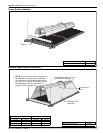
GAS PIPING
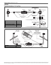
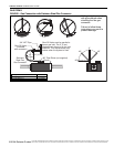
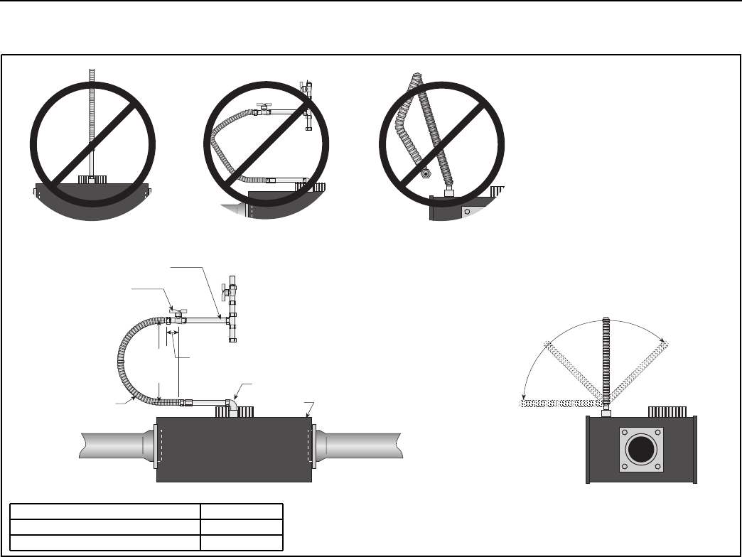
FIGURE 1: Gas Connection with Stainless Steel Flex Connector
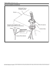
Hold gas nipple securely
with pipe wrench when
attaching the flex gas
connector.
Failure to follow these
instructions can result in
product damage.
Burner
2" (5 cm)
Stainless
Steel Flex
Gas Connector
Shut-Off Valve
(included
with connector)
3/4" NPT Pipe
Shut-Off Valve must be parallel to
burner gas inlet. The 2" (5 cm)
displacement shown is for the cold
condition. This displacement may
reduce when the system is fired.
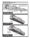
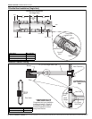
12"
(30 cm)
45°
90°
0°
45°
90° Pipe Elbow (not supplied)
Description Part Number
1/2” Flex Gas Line 91412200
3/4” Flex Gas Line 91412203