


ROBERTS GORDON
®
TF-SERIES SUBMITTAL SHEET
© 2004 Roberts-Gordon
APPLICATIONS, ENGIN EERING AND DETAI LED GUIDANCE ON SYSTEMS DESIGN, INSTALLATION AND PRODUCT PERFORMANCE IS AVAILABLE UPO N REQUEST. ROBERTS GORDON
®
PRODUCTS ARE TO BE
INSTALLED ONLY I N ACCOR DANCE WITH LOCAL LAW S, CODES AND REGULAT IONS, AND ONLY BY A CONTRACTO R QUALIFIED IN THE INST ALLATION AND SERVICE OF GAS-F IRED HEATING EQUIPMEN T.
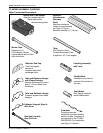
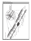
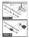
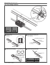
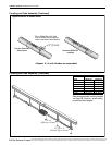
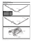
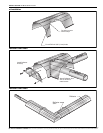
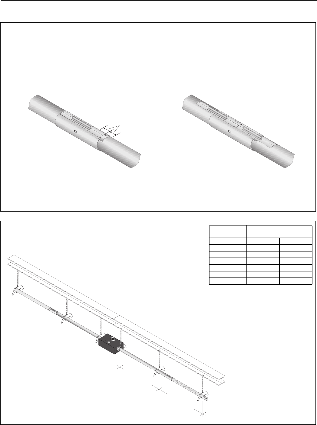
Coupling and Tube Assembly (Continued)
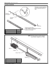
Coupling and Tube Assembly (Continued)
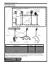
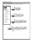
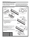
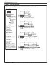
Incorrect Slide Bar
position
Correct Slide Bar
dimensions
± 2" (5 cm)
Drive Slide Bar until tight.
End of Slide Bar should be
within tolerance listed below.
• Repeat A - D until all tubes are assembled.
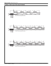
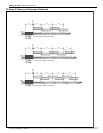
Tighten slide bar as shown below
10' Typ. ± 1'
(254 cm Typ ± 25 cm)
7' 6" ± 1'
(229 cm ± 25 cm)
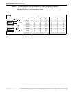
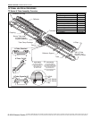
Model
Tube Length Per Side
Minimum Maximum
TF-120 20’ (6 m) 20’ (6 m)
TF-160 20’ (6 m) 30’ (9 m)
TF-200 30’ (9 m) 40’ (12 m)
TF-250 40’ (12 m) 50’ (15 m)
TF-300 50’ (15 m) 60’ (18 m)
TF-350 50’ (15 m) 70’ (21 m)
TF-380 60’ (18 m) 80’ (24 m)
See recommended venting lengths
on Page 28, Section , when using
maximum tube lengths.