


ROBERTS GORDON
®
TF-SERIES SUBMITTAL SHEET
© 2004 Roberts-Gordon
APPLICATIONS, ENGIN EERING AND DETAI LED GUIDANCE ON SYSTEMS DESIGN, INSTALLATION AND PRODUCT PERFORMANCE IS AVAILABLE UPO N REQUEST. ROBERTS GORDON
®
PRODUCTS ARE TO BE
INSTALLED ONLY I N ACCOR DANCE WITH LOCAL LAW S, CODES AND REGULAT IONS, AND ONLY BY A CONTRACTO R QUALIFIED IN THE INST ALLATION AND SERVICE OF GAS-F IRED HEATING EQUIPMEN T.
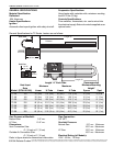
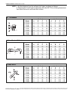
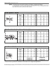
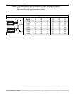
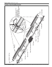
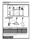
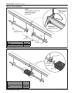
NOTE: 1. All dimensions are from the surfaces of all tubes, couplings and elbows.
2. Clearances B, C and D can be reduced by 50% after 25' (7.5 m) of tubing downstream
from where the burner and burner tube connect.
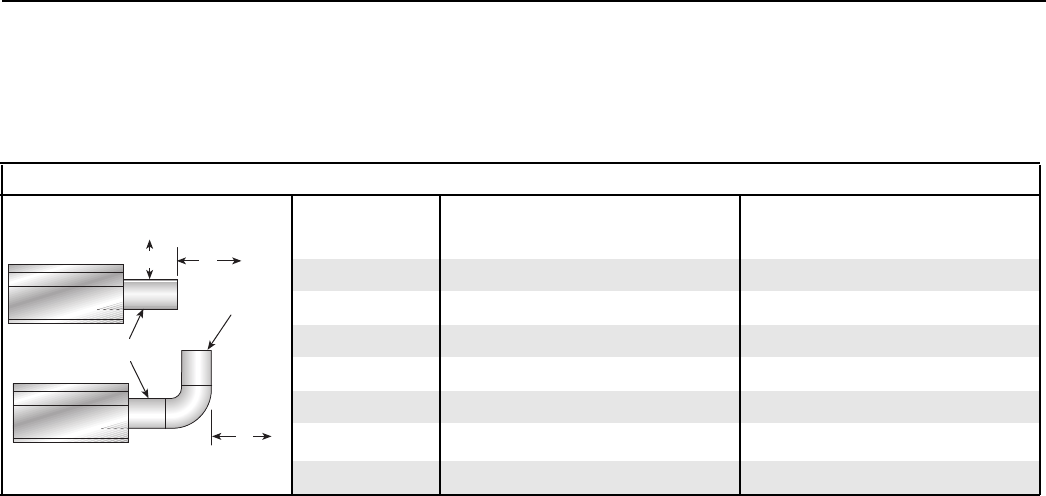
Venting
(inches) (centimeters)
Model A E F A E F
TF-120 14 18 18 36 46 46
TF-160 20 24 18 51 61 46
TF-200 20 24 18 51 61 46
TF-250 20 24 18 51 61 46
TF-300 20 30 18 51 77 46
TF-350 20 30 18 51 77 46
TF-380 20 30 18 51 77 46
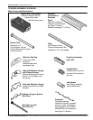
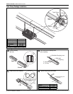
Infrared Tubes
Vent
Pipes
Unvented
Vented
A
E
F