


TABLE OF FIGURES
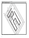
Figure 1: Example Site Layout ..................................................6
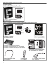
Figure 2: ROBERTS GORDON
®
ULTRAVAC™ Controller
Specifications ............................................................8
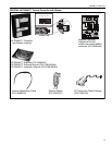
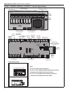
Figure 3: Variable Frequency Drive Components
(Factory pre-wiring shown) ...................................... 10
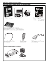
Figure 4: Controller Mounting.................................................. 11
Figure 5: Indoor Sensor Cable Detail......................................12
Figure 6: Outdoor Sensor, VFD (0-10 V) Signal, RS-485
Communications Cable and
Pressure Switch Cable Detail................................... 12
Figure 7: Variable Frequency Drive Mounting......................... 13
Figure 8: Indoor Sensor Mounting .......................................... 14
Figure 9: Outdoor Sensor Placement ..................................... 14
Figure 10: Central Controller Communication Equalization
Wiring..................................................................... 15
Figure 11: ROBERTS GORDON
®
ULTRAVAC™ Central
Controller External Wiring ......................................16
Figure 12: ROBERTS GORDON
®
ULTRAVAC™ Satellite
Controller External Wiring ......................................18
Figure 13: Modem Location ....................................................20
Figure 14: RS-485 PC Connection..........................................21
Figure 15: TCP/IP Communication Module Mounting.............22
Figure 16: TCP/IP Communication Module Wiring..................23
Figure 17: 9 Pin Adapter for PC ..............................................24
Figure 18: Communications Between Multiple Controllers......25
Figure 19: Repeater Wiring .....................................................26
Figure 20: End Vent Vacuum ..................................................30
Figure 21: Possible Damper Couplings’ Locations..................31
Figure 22: ROBERTS GORDON
®
ULTRAVAC™ Controller
Components Diagram ............................................33
Figure 23: Variable Frequency Drive Components Diagram...34
Figure 24: Troubleshooting Flow Chart ...................................37