


ROBERTS GORDON
®
ULTRAVAC™ CONTROLLER INSTALLATION MANUAL
8
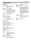
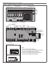
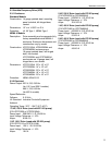
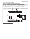
FIGURE 2: ROBERTS GORDON
®
ULTRAVAC™ Controller Specifications
+-
1
+-
2
+-
4
+-
3
+-
5
+-
6
+-
7
+-
8
+- +-
REF
24VAC
L2
NONC C
NONC CNONC CNONC CNONC C
NONC CNONC CNONC C
RS485 COMM
REF
+-
1
+-
2
+-
3
+-
4
METER INPUTS
UNIVERSAL INPUTS
INOUT
ADDRESS
RESET
10VDC
499 OHM
OFF
ON
OUT
IN
GINOUT GGG
+5
+32
AUX POWER
RS232 DIRECT
RI
CDOH
CPU
L1
PWR
+-
1
+-
2
+-
4
+-
3
+-
5
+-
6
+-
7
+-
8
+- +-
REF
24VAC
L2
NONCC
NONCCNONCCNONCCNONCC
NONCCNONCCNONCC
RS485 COMM
REF
+-
1
+-
2
+-
3
+-
4
METER INPUTS
UNIVERSAL INPUTS
INOUT
ADDRESS
RESET
10VDC
499 OHM
OFF
ON
OUT
IN
GINOUT G GG
+5
+32
AUX POWER
RS232 DIRECT
RI
CDOH
CPU
L1
PWR
POWER
L1 L2 GRD
OUTPUT 1
L1 L2 GRD
OUTPUT 2
L1 L2 GRD
OUTPUT 3
L1 L2 GRD
OUTPUT 4
L1 L2 GRD
OUTPUT 5
L1 L2 GRD
OUTPUT 6
L1 L2 GRD
OUTPUT 7
L1 L2 GRD
OUTPUT 8
L1 L2 GRD
120 Vac Outputs
Plug-In
Relays
24 V
Power
Switch
Control
Board
Transformer
Meter Inputs
Analog
Output
Board
Modem
Phone Port
Analog Inputs
Eprom
Chip
Selector
Switch
Reset
Button
RS 485
Terminals
RS 232
Direct Connect
Port
24 V Board
Power Input
24 V Control Board
Power Supply
Relay Board
24 V
Power
1 A Fuse
Sensor
Power
120 Vac Power Input
Modem Chip
(optional - only located
on Controller #1)
24 V
Outputs
24 V Outputs
24 V Input
Connections
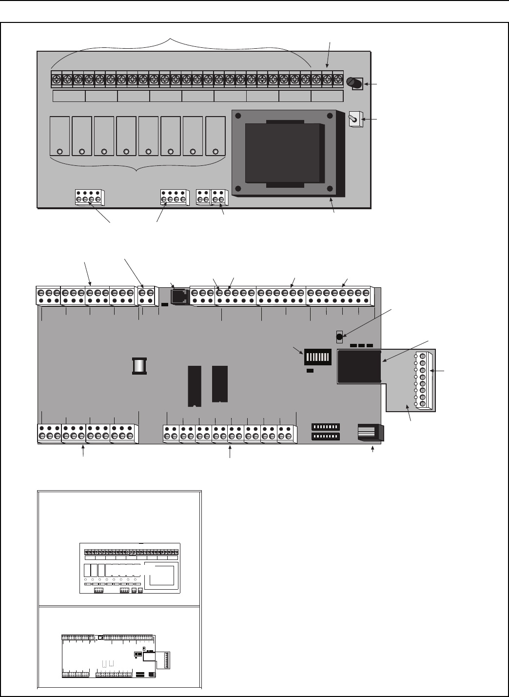
Controller Enclosure
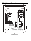
OUTPUT 1
L1
L2
GRD
GRD
L2
L1
OUTPUT 2
GRD
L2
L1
OUTPUT 3
GRD
L2
L1
OUTPUT 4
GRD
L2
L1
OUTPUT 5
GRD
L2
L1
OUTPUT 6
GRD
L2
L1
OUTPUT 7
GRD
L2
L1
OUTPUT 8
GRD
L2
L1
POWER
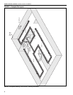
Line Voltage 120 V wiring
Relay Board
Low Voltage 24 V wiring
Control Board
5 V TCP/IP
Module
Power
Analog
Outputs
Note:
To ensure robust control signaling:
Do not run line voltage wiring through bottom section
of enclosure that houses the control board.
Do not run low voltage wiring through top section
of enclosure that houses the relay board.