


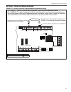
SECTION 4: TYPICAL EXTERNAL DIAGRAMS
19
ROBERTS GORDON
®
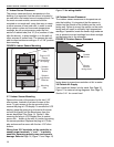
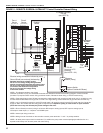
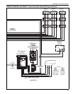
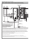
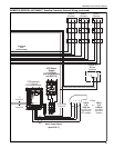
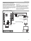
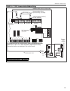
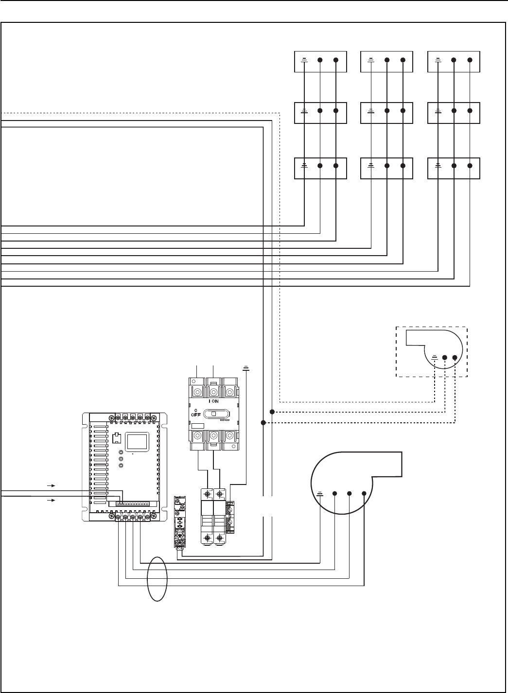
ULTRAVAC™ Satellite Controller External Wiring (continued)
L1L2
T
1
L1L2
L1L2
L1L2
L1L2
L1L2
L1L2
Zone 3
Burners
L1L2
L1L2
Zone 2
Burners
Zone 1
Burners
To Terminals
13 and 14
T
2
T
3
Continued
From
Previous Page
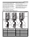
Motor Power Supply
(See NOTE 7)
Pump
230 V
3 Ø
0-60 Hz
for 115 V and
230 V input
VFD models.
460 V
3 Ø
0-60 Hz
for 460 V
input VFD
models.
or
Outside Air
Blower
(optional)
VFD Power
Supply
(1 Ø input
VFD model shown,
see NOTE 3)
VFD Assembly
( 1 Ø input
VFD model shown)
To
Terminal 5
To
Terminal 2
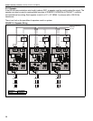
M16/12.PM16/12.P
1
2
5
6
11
13A
13B
13E
25
16
17
PEPEWVU
L2/NL1 B-PE
B+