


SECTION 3: INSTALLATION
11
SECTION 3: INSTALLATION
Installation of the ROBERTS GORDON
®
ULTRAVAC™ Controller and the associated external
electrical wiring must be done by an electrician
qualified in the installation of control systems for
heating equipment.
3.1 Preparation
Before installing the controller, observe the following:
3.1.1 Ensure that you have a copy of the site layout
for the project that clearly identifies the separate
zones.
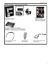
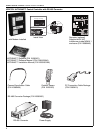
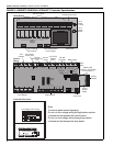
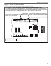
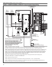
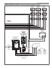
3.1.2 Familiarize yourself with the Controller and Vari-
able Frequency Drive component names and loca-
tions. See Page 8, Figure 2 and Page 10, Figure 3.
3.2 Positioning the ROBERTS GORDON
®
ULTRAVAC™ Controller and Variable Frequency
Drive
3.2.1 Choose a mounting location for the controller.
Generally near the pump, a dedicated phone con-
nection (optional) and the variable frequency drive.
For serviceability, it is convenient to mount the con-
troller and variable frequency drive at occupant level
in the vicinity of the pump.
Do not mount controller or VFD outdoors. VFD
must not be installed where subjected to adverse
conditions such as: combustible, oily, or hazard-
ous vapors or dust; excessive moisture or dirt;
vibration. To avoid damage from possible drips,
do not mount controller or VFD directly beneath
pump. Models with NEMA 4 rated enclosures will
withstand exposure to dust, dirt and water.
VFD should be mounted in locations where the
maximum ambient temperature does not exceed
104°F (40°C). Avoid installing the VFD in mezza-
nines, direct sunlight, or near external heat
sources because these locations usually have
unpredictable temperature rises.
Note that the maximum distance from the controller
to any sensor is 300' (120 m). For longer distances,
larger gauge wire may be needed (Consult your local
distributor). For multiple controllers, maximum length
of communication wire from the first controller to the
last is 4000' (1219 m).
3.2.2 Position the controller and VFD at occupant
level for ease of service. To avoid electrical
interferences with communications bus, do not
mount VFD directly next to controller. Allow 2'
(.6 m) minimum between controller and VFD.
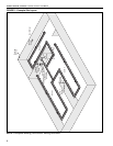
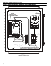
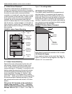
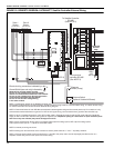
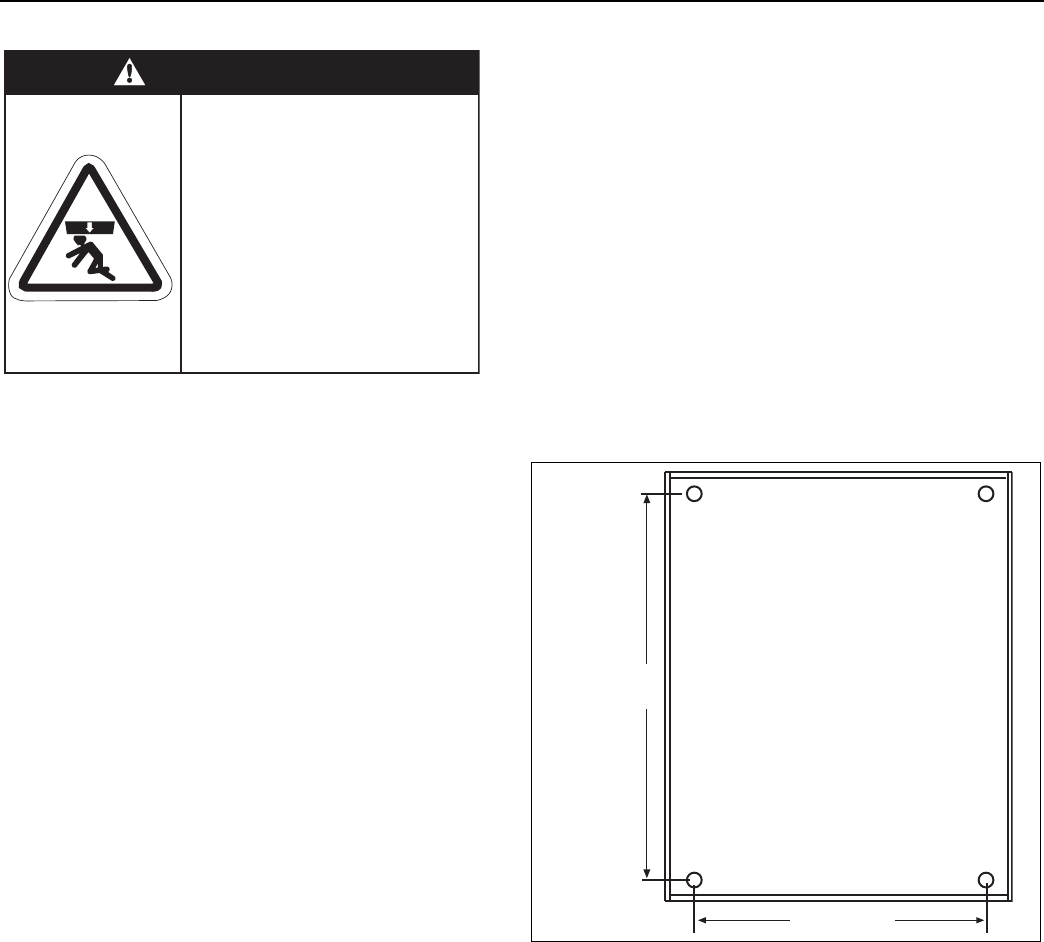
FIGURE 4: Controller Mounting
(Standard enclosure only, NEMA 4 enclosure mount-
ing varies)
WARNING
Severe Injury Hazard
Mount controls with
materials with a minimum
working load of 75 lbs
(33 kg).
Failure to follow these
instructions can result in
death, injury or property
damage.
13" (33 cm)
16.25"
(41.3 cm)