


ROBERTS GORDON
®
ULTRAVAC™ CONTROLLER INSTALLATION MANUAL
22
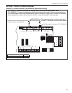
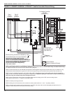
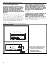
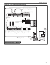
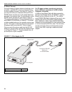
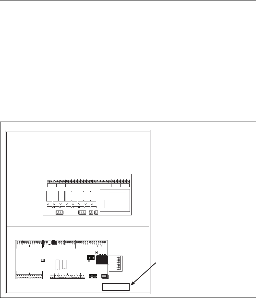
5.3 TCP/IP Communication Module
For remote on-site viewing of system status and
settings of any controller, use the TCP/IP communi-
cation module to connect the controllers to a Local
Area Network (LAN) via Ethernet cable. Any
computer on the LAN that has ULTRAVAC™ soft-
ware installed can be used to communicate with the
controllers.
The module must be mounted inside the
ULTRAVAC™ central controller (controller #1)
enclosure next to the control board. The power (5V)
for the module will come from the ULTRAVAC™
control board. The module will communicate to the
controller via regular phone wire from the RJ11 jack
on the module to the RS-232 direct connect port on
the control board. The module will relay the data
from the controller to computers on the LAN via
Ethernet cable plugged into the RJ45 jack on the
module. A setup procedure must be performed on
the module upon installation to create its IP address
on the LAN. The setup instructions can be found in
the ROBERTS GORDON
®
Software Manual.
For TCP/IP communication module wiring details,
see
Page 23, Figure 16
.
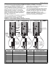
If multiple ULTRAVAC™ controllers are being used, the
additional controllers communicate to controller #1
through RS-485 communication wiring arranged
in-series from one controller to the next.
See Page 25,
Section 5.5
.
This allows multiple controllers to be
controlled from a PC through a single communication
package at the central controller.
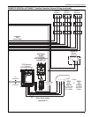
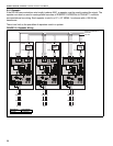
FIGURE 15: TCP/IP Communication Module Mounting
Controller Enclosure
OUTPUT 1
L1
L2
GRD
GRD
L2
L1
OUTPUT 2
GRD
L2
L1
OUTPUT 3
GRD
L2
L1
OUTPUT 4
GRD
L2
L1
OUTPUT 5
GRD
L2
L1
OUTPUT 6
GRD
L2
L1
OUTPUT 7
GRD
L2
L1
OUTPUT 8
GRD
L2
L1
POWER
Line Voltage 120 V Wiring
Relay Board
Low Voltage 24 V Wiring
Mount TCP/IP module to enclosure
here or other suitable location within
the control board's compartment.
Do not mount module
in relay board compartment.
PSC CONTROLLER
+-
1
+-
2
+-
4
+-
3
+-
5
+-
6
+-
7
+-
8
+- +-
REF
24VAC
L2
NO
NC C
NONC CNO
NC
CNO
NC CNONCC
NONC CNONC CNONCC
RS485 COMM
REF
+-
1
+-
2
+-
3
+-
4
METER INPUTS
UNIVERSAL INPUTS
INOUT
ADDRESS
RESET
10VDC
499 OHM
OFF
ON
OUT
IN
GINOUT GGG
+5
+32
AUX POWER
RS232 DIRECT
RI
CDOH
CPU
L1
PWR
Control Board