


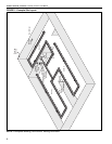

ROBERTS GORDON
®
ULTRAVAC™ CONTROLLER INSTALLATION MANUAL
14
3.7 Indoor Sensor Placement
The sensor measures the air temperature in the
building. It is important that the sensor is located in
an area within the heated zone at occupant level. For
the most accurate results, sensors should be
mounted on an inside wall, away from any air vents
or other sources of heat and cold. In order to avoid
short system cycles and inaccurate temperature
readings, do not mount sensors under the first
section of radiant tube (first 10' (3 m) section of tube
after the burner), in direct sunlight or in the path of
other sources of radiant heat. The sensors are suit-
able for direct surface mounting or 4" x 2 1/8" junction
box mounting.
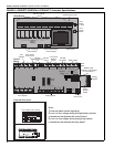
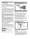
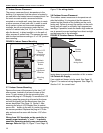
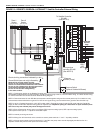
FIGURE 8: Indoor Sensor Mounting
3.7.1 Indoor Sensor Mounting
Remove the cover of the sensor by the two 1/16"
allen screws, located in the lower corners of the
cover. To gain access to the top mounting hole,
remove the plug-in LCD display. To remove the LCD
display, grasp the green plug-in board at the lower
corners and gently pull the board away from the
sensor back plate. See Page 14, Figure 8. After
removing the plug-in LCD display from its socket,
secure the sensor to the wall or junction box using
the screws provided. Replace the plug-in LCD dis-
play and secure the cover with the two 1/16" allen
screws.
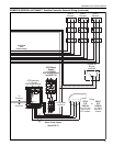
Wiring from 32 V terminals on the controller to
sensor power terminals "+" and "-" is polarity
sensitive. Reversing polarity may cause sensor
damage. Refer to Page 16, Figure 11 and Page 18,
Figure 12 for wiring details.
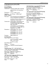
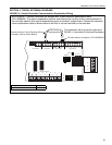
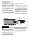
3.8 Outdoor Sensor Placement
The outdoor sensor measures air temperature out-
side the building. It is important that the sensor is
located on the outside of the building on the north
facing wall. Failure to mount the sensor on the north
facing wall will result in artificially high temperature
readings. If possible, locate the sensor high under an
eve to prevent incorrect readings from direct sunlight
and damage due to the elements.
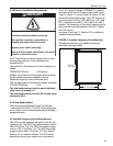
FIGURE 9: Outdoor Sensor Placement
Mount the outside sensor with the sensor module
facing down to prevent accumulation of dirt or water.
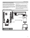
3.9 Outside Air Supply
If an outside air blower is to be used, See Page 16,
Figure 11 for external wiring diagrams. See Page 13,
Section 3.4.1 for current load.
SEN SET O/R
-+
Mounting
Hole
Plug-in LCD
Display
(grasp here
to unplug)
Mounting
Hole
Setback
Override
Button
Setpoint
Adjustment
Slide bar
North
Outside
Sensor
Sensor
Module
facing down