


SECTION 5: COMMUNICATIONS
25
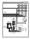
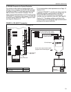
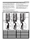
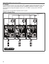
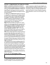
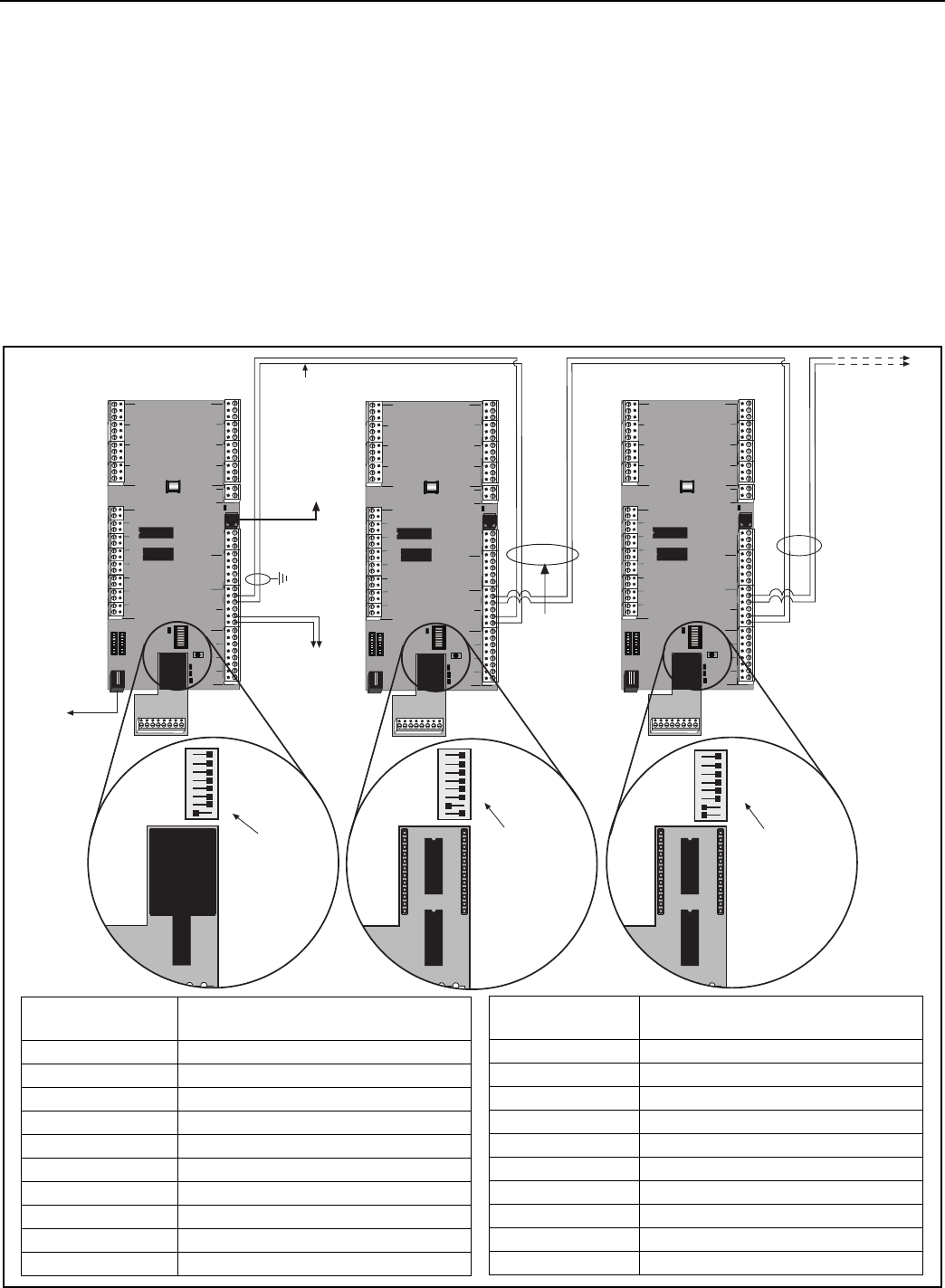
5.5 Communications Between Multiple ROBERTS GORDON
®
ULTRAVAC™ Controllers
If more than one ROBERTS GORDON
®
ULTRA-
VAC™ Controller is installed in a building, the
controllers’ RS-485 communications must be wired in
series. See Page 25, Figure 18. Connect the
RS-485 terminal on controller
#
1 to the RS-485
terminal on controller
#
2 and so on in a daisy chain
fashion. For communication cable requirements,
See Page 12, Section 3.3.5
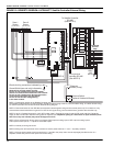
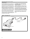
From a PC, by dialing into the modem on controller
#
1
or by connecting to controller
#
1 via RS-485
converter or TCP/IP communication module, the
system status and settings can be viewed for any of
the controllers on the network.
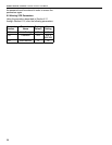
The control board identification dip switch must be
set on each ROBERTS GORDON
®
ULTRAVAC™
Controller. See Page 25, Figure 18 for dip switch
settings. Contact Roberts-Gordon or your
ROBERTS GORDON
®
independent distributor, if
more than 20 controllers are connected.
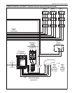
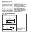
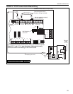
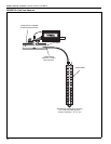
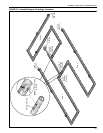
FIGURE 18: Communications Between Multiple Controllers
+-
1
+-
2
+-
4
+-
3
+-
5
+-
6
+-
7
+-
8
+- +-
REF
24VAC
L2
NONC C
NONC CNONC CNONC CNONCC
NONC CNONC CNONCC
RS485 COMM
REF
+-
1
+-
2
+-
3
+-
4
METER INPUTS
UNIVERSAL INPUTS
INOUT
ADDRESS
RESET
10VDC
499 OHM
OFF
ON
OUT
IN
GINOUT G G G
+5
+32
AUX POWER
RS232 DIRECT
RI
CDOH
CPU
L1
PWR
+-
1
+-
2
+-
4
+-
3
+-
5
+-
6
+-
7
+-
8
+- +-
REF
24VAC
L2
NONC C
NONC CNONC CNONC CNONCC
NONC CNONC CNONCC
RS485 COMM
REF
+-
1
+-
2
+-
3
+-
4
METER INPUTS
UNIVERSAL INPUTS
INOUT
ADDRESS
RESET
10VDC
499 OHM
OFF
ON
OUT
IN
GINOUT G G G
+5
+32
AUX POWER
RS232 DIRECT
RI
CDOH
CPU
L1
PWR
+-
1
+-
2
+-
4
+-
3
+-
5
+-
6
+-
7
+-
8
+- +-
REF
24VAC
L2
NONC C
NONC CNONC CNONC CNONCC
NONC CNONC CNONCC
RS485 COMM
REF
+-
1
+-
2
+-
3
+-
4
METER INPUTS
UNIVERSAL INPUTS
INOUT
ADDRESS
RESET
10VDC
499 OHM
OFF
ON
OUT
IN
GINOUT G G G
+5
+32
AUX POWER
RS232 DIRECT
RI
CDOH
CPU
L1
PWR
RS 485
Wiring
Central Controller
(controller
#
1)
Satellite Controller
(controller
#
2)
To Additional
Controllers
Wiring
to RS 485
Converter
at PC
(optional)
Dedicated
Outside
Phone Line
(optional)
℡
Satellite Controller
(controller
#
3)
Dip Switch
#
1 and
#
2
Set to ON
(controller
address
#
3)
1 2 3 4 5 6 7 8
Dip Switch
#
2
Set to ON
(controller
address
#
2)
1 2 3 4 5 6 7 8
To RJ11
connection on
TCP/IP
Module
(optional)
Dip Switch
#
1
Set to ON
(controller
address
#
1)
Modem
Chip
1 2 3 4 5 6 7 8
Ground
Shield
Join Shields -
Do Not Ground
Join Shields -
Do Not Ground
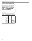
Controller
Number
Dip Switch Order (1,2,3,4,5,6,7,8)
Values (1=ON, 0=OFF)
11 11010000
12 00110000
13 10110000
14 01110000
15 11110000
16 00001000
17 10001000
18 01001000
19 11001000
20 00101000
Controller
Number
Dip Switch Order (1,2,3,4,5,6,7,8)
Values (1=ON, 0=OFF)
1 (Central Controller) 10000000
2 01000000
3 11000000
4 00100000
5 10100000
6 01100000
7 11100000
8 00010000
9 10010000
10 01010000