


ROBERTS GORDON
®
ULTRAVAC™ CONTROLLER INSTALLATION MANUAL
18
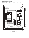
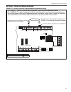
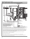
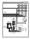
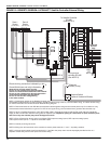
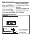
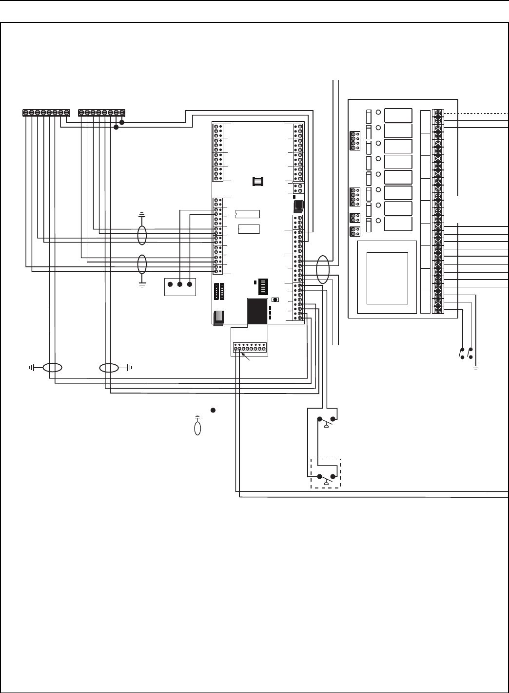
FIGURE 12: ROBERTS GORDON
®
ULTRAVAC™ Satellite Controller External Wiring
ADDRESS
RESET
10VDC
499 OHM
OFF
ON
OUT
IN
RICDOH
CPU
BMS Enable
(optional)
NC C NO
To Satellite Controller
RS-485
(See NOTE 2)
120 V
1 Ø
60 Hz
POWER
L1 L2 GRD
OUTPUT 1
L1 L2 GRD
OUTPUT 2
L1 L2 GRD
OUTPUT 3
L1 L2 GRD
OUTPUT 4
L1 L2 GRD
OUTPUT 5
L1 L2 GRD
OUTPUT 6
L1 L2 GRD
OUTPUT 7
L1 L2 GRD
OUTPUT 8
L1 L2 GRD
Pressure
Switch (Pump)
Join Shields - Do Not Ground
From previous
controller RS-485
(See NOTE 2)
Pressure Switch
(Optional Outside Air Blower)
Zone 1
Sensor
(see NOTE 6)
Zone 2
Sensor
(see NOTE 6)
+-
O/RSETSEN O/RSETSEN
+-
Electrical wiring connections indicated by a dot;
(See NOTE 2)
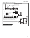
Continued
On Next
Page
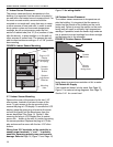
Separate line and low voltage circuits.
Do not run line voltage wiring through bottom
section of enclosure that houses the control board.
Do not run low voltage wiring through top section
of enclosure that houses the relay board.
Do not run line and low voltage wiring
in the same conduit.
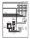
NOTE 1: This diagram applies to the Satellite Controller only.
The Satellite Controller does not require modem, RS-485 converter wiring to the PC, TCP/IP module wiring, or outdoor sensor wiring.
For Central Controller see Central Controller External Wiring Diagram.
NOTE 2: Twist shield wires for both RS-485 communication cables together and ground at central panel only. On controller #1 only,
connect these twisted shield wires to ground. For VFD 0-10 V signal wiring, connect shield wire to ground at the controller only.
NOTE 3: 120 V 1 Ø 50-60 Hz supply for 120 V VFD model. 230V 1 Ø 50-60 Hz supply for 230 V VFD model. 460 V
3 Ø 50-60 Hz
supply for 460 V VFD model. See VFD rating plate for required input. Repetitive cycling of a disconnect or input contactor (more
than once every two minutes) may cause damage to the drive.
NOTE 4: Zone 3 Sensor(not shown) wiring is as follows: SEN output to analog input 3; SET output to analog input 6;
O/R output to meter input 3; +/- outputs to +32 V/GND inputs.
NOTE 5: Internal pre-wiring not shown.
NOTE 6: Wiring from 32 V terminals on the controller to sensor power terminals "+" and "-" is polarity sensitive.
NOTE 7: All three power output wires from terminals U, V, and W to the pump motor must be kept tightly bundled and run in a
separate condu
it away from all other power and control wiring.
24VAC
L2 L1
PWR
NC C NO
NC C NO
NC C NO
NC C NO
NC C NO
NC C NO
NC C NO
NC C NO
+- +-
REF
RS485 COMM
REF
+-
1
+-
2
+-
3
+-
4
METER INPUTS
INOUT
GINOUT G G
G
+5
+32
AUX POWER
RS232 DIRECT
+
-
1
2
4
3
5
6
8
UNIVERSAL INPUTS
+
-
+
-
+
-
+
-
+
-
+
-
+
-
7
Ground Shield (one end only) indicated by;
M16/12.P