


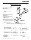

Regency P33R-2 Zero Clearance Rear Vent Direct Vent Gas Fireplace
9
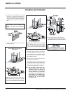
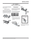
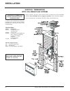
"C" Screw Position:
For a facing material depth of
1-1/4"(32mm), the top facing
support must be reversed.
The Top Facing Support, the Side Nailing Strips
and the 2 Top Standoffs must be correctly
positioned and attached to the top before unit
is slipped into position.
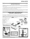
Top Standoff Assembly
The top standoffs are shipped in a flat position
and must be pulled up and bent into the correct
shape. Setup each of the 2 Top Standoff by
bending up at the bend lines until the screw hole
in the standoff and the pre-punched screw
holes on the top line up. Use three more screws
per standoff to attach securely to the top.
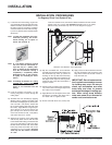
Top Facing Support &
Side Nailing Strips
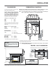
Determine the total thickness of facing material
(e.g. drywall plus ceramic tiles) to allow the
finished surface to be flush with the front of the
unit. Total facing thickness can vary from 1/2"
(13mm) to 1-1/4" (32mm) thick.
The Top Facing Support & Side Nailing Strips
can be mounted in 3 different positions depend-
ing on the thickness of the facing material.
Screw Facing Material
Position Depth
A 1/2" / 13mm
B 7/8" / 22mm
C* 1-1/4" / 32mm
* For "C" screw position the top facing support
is reversed.
1) Mount Top Facing Support using the 3
supplied screws into the three pre-punched
screw holes on the top front of the unit. Use
hole positions A, B, or C depending on your
facing depth.
2) Use the same screw hole position for the
Side Nailing Strips as was used for the Top
Facing Support. Attach each side nailing
strip using 3 screws.
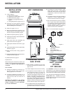
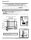
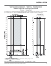
UNIT ASSEMBLY
PRIOR TO INSTALLATION
INSTALLATION