


Regency P33R-2 Zero Clearance Rear Vent Direct Vent Gas Fireplace
7
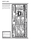
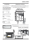
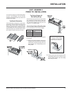
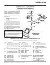
COMBUSTIBLE MANTELS
INSTALLATION
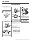
Clearances for Bay or Flush Front
WARNING
Fire hazard is an extreme risk if
these clearances are not ad-
hered to.
Because of the extreme heat this fireplace emits, the mantel clearances are critical.
Combustible mantel clearances from top of unit are shown in the diagram below.
Note: A non-combustible mantel may be installed at a lower height if the framing is
made of metal studs covered with a non-combustible board.
MANTEL LEG CLEARANCES
Combustible mantel leg clearances as per diagram below:
This drawing is to scale at 1:6 (one inch = 6 inches). Mantel can be installed anywhere in shaded
area or higher using the above scale.
Note: Ensure the paint that is used on the mantel and the facing is "heat resistant"
or the paint may discolour.
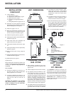
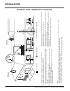
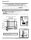
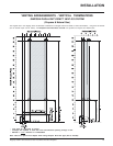
CLEARANCES
The clearances listed below are Minimum dis-
tances unless otherwise stated:
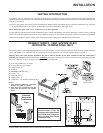
A major cause of chimney related fires is
failure to maintain required clearances
(air space) to combustible materials. It is
of the greatest importance that this fire-
place and vent system be installed only in
accordance with these instructions.
Clearance to Combustibles from:
Back 0" (0mm)
Side 0" (0mm)
Floor 0" (0mm)
NOTE: The minimum floor clearance must be
maintained from the top surface of the carpet-
ing, tile, etc.
Minimum Clearance from Top of Unit to:
Mantel* min. 7" (177mm)
Ceiling 30" (762mm) from
top of unit.
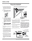
Side Wall Clearance
Bay or Flush Front 7-1/2" (191mm)
Maximum
1-1/2"
projection at
2" minimum
clearance.
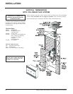
The HeatWave Duct Kit has different
clearance and framing requirements,
check the HeatWave manual for details.
Vent 1-1/2" (38mm) Flex
1-1/4" (32mm) Simpson Dura-Vent
Alcove Clearances:
Max. Depth 36" (914mm)
Min. Width 48" (1219mm)
Min. Height 59" (1499mm)
* see mantle clearance instructions (page 7).