


Regency P33R-2 Zero Clearance Rear Vent Direct Vent Gas Fireplace
8
INSTALLATION
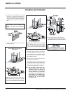
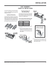
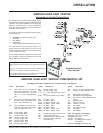
Install Side Nailing Strips, and Top Facing
Support before unit is slipped into
position. See page 9 for assembly
details.
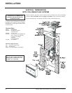
3) For exterior walls, insulate the enclosure to
the same degree as the rest of the house,
apply vapour barrier and drywall, as per
local installation codes. (Do not insulate
the fireplace itself.)
4) The top of the unit must not be closer than
30" (762mm) to the ceiling.
5) Combustible material may be brought up to
the top and sides of the unit and be covered
with ceramic tiles, bricks, rock or other
suitable combustible finishing materials.
Note: The unit does not have to be com-
pletely enclosed in a chase. The
clearance on top of the unit is 0" to
the standoffs so combustible
building materials can be laid di-
rectly on top of the standoffs. You
must maintain 1-1/2" (38mm) clear-
ance from the vent to combustible
materials for flex (1-1/4" for Simp-
son Dura-Vent).
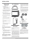
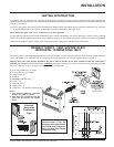
1) Determine the total thickness of facing
material (e.g. drywall plus ceramic tiles) to
allow the finished surface to be flush with
the front of the unit. Total facing thickness
can vary from 1/2" (13mm) to 1-1/4" (32mm)
thick.
6) Use steel studs for framing where the
1-1/2" (38mm) clearance from the vent to
combustible material cannot be maintained.
2) Frame in the enclosure for the unit with
framing material.
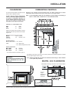
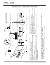
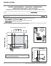
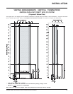
Vertical Termination or
Vertical Rise with Horizontal
Termination
Rear Termination
FRAMING AND FINISHING
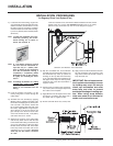
NOTE: If this is an outside corner, the minimum
distance between the vent and the outside
corner is 6" (15cm) with AstroCap termination
cap or 12" (30cm) with Dura-Vent termination
cap.
NOTE: If this is an outside corner, the minimum
distance between the vent and the outside
corner is 6" (15cm) with AstroCap termination
cap or 12" (30cm) with Dura-Vent termination
cap.
The HeatWave Duct Kit has different
clearance and framing requirements,
check the HeatWave manual for details.