


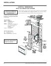
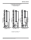

Regency P33R-2 Zero Clearance Rear Vent Direct Vent Gas Fireplace
20
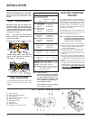
P33R-2 System Data
For 0 to 4500 feet altitude
Burner Inlet Orifice Sizes:
Natural Gas Propane
Burner #45 #54
Max. Input Rating
- Natural Gas 21,000 Btu/h
- Propane 21,000 Btu/h
Min. Input Rating
-Natural Gas 10,500 Btu/h
-Propane 10,500 Btu/h
Output Capacity with blower Off
Natural Gas 15,960 Btu/h
Propane 16,170 Btu/h
Output Capacity with blower On
Natural Gas 16,170 Btu/h
Propane 16,380 Btu/h
Minimum Output with blower Off
Natural Gas 7,980 Btu/h
Propane 8,085 Btu/h
Supply Pressure
Natural Gas min. 5.0" w.c.
Propane min. 12.0" w.c.
Manifold Pressure (High)
Natural Gas 3.8" +/- 0.2" w.c.
Propane 11" +/- 0.2" w.c.
Electrical: 120 V A.C. System.
Circulation Fan: variable speed 130 CFM.
Log Set: Ceramic fibre, 5 per set.
Vent System: Simpson Dura-Vent Direct
Vent System or Regency Direct
Vent System (Flex)
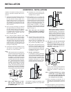
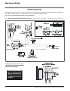
GAS PIPE PRESSURE
TESTING
The appliance must be isolated from the gas
supply piping system by closing its individual
manual shut-off valve during any pressure
testing of the gas supply piping system at test
pressures equal to or less than 1/2 psig.
(3.45 kPa). Disconnect piping from valve at
pressures over 1/2 psig.
The manifold pressure is controlled by a reg-
ulator built into the gas control, and should be
checked at the pressure test point.
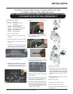
Note: To properly check gas pressure,
both inlet and manifold pressures
should be checked using the valve
pressure ports on the valve.
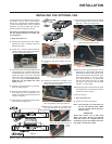
1) Make sure the valve is in the "OFF" position.
2) Loosen the "IN" and/or "OUT" pressure
tap(s), turning counterclockwise with a 1/
8" wide flat screwdriver.
3) Attach manometer to "IN" and/or "OUT"
pressure tap(s) using a 5/16" ID hose.
4) Light the pilot and turn the valve to "ON"
position.
5) The pressure check should be carried out
with the unit burning and the setting should
be within the limits specified on the safety
label.
6) When finished reading manometer, turn off
the gas valve, disconnect the hose and
tighten the screw (clockwise) with a 1/8"
flat screwdriver. Note: Screw should be
snug, but do not over tighten.
INSTALLATION
Important: Always check for gas leaks
with a soap and water solution or gas leak
detector. Do not use open flame for leak
testing.
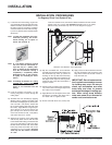
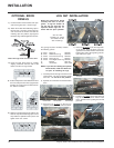
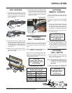
PILOT ADJUSTMENT
Periodically check the pilot flames. Cor-
rect flame pattern has three strong blue
flames: 1 flowing around the thermopile,
1 around the thermocouple and 1 flowing
across the burner (it does not have to be
touching the burner).
Note: If you have an incorrect flame
pattern, contact your Regency dealer for
further instructions.
Incorrect flame pattern will have small,
probably yellow flames, not coming into
proper contact with the rear burner or
thermopile or thermocouple.
HIGH ELEVATION
This unit is approved in Canada for altitude 0 to
4500 ft. (CAN1 2.17-M91) with the orifice
supplied.
Note: Output capacity:
The efficiency rating of the appli-
ance is a product thermal efficien-
cy rating determined under con-
tinuous operating conditions and
was determined independently of
any installed system.
Vent height may or may not change
your efficiency ratings.
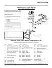
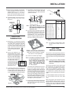
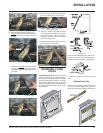
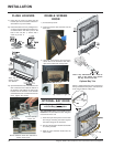
S.I.T. VALVE DESCRIPTION
1) Gas cock knob
2) Manual high/low adjustment
3) Pilot Adjustment
4) Thermocouple Connection - option
5) Outlet Pressure Tap
6) Inlet Pressure Tap
7) Pilot Outlet
8) Main Gas Outlet
9) Alternative TC Connection Point