


Regency P33R-2 Zero Clearance Rear Vent Direct Vent Gas Fireplace
27
INSTALLATION
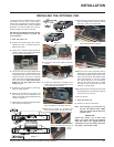
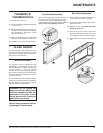
INSTALLING THE OPTIONAL FAN
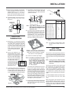
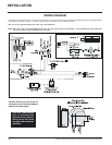
120 Volt AC power is needed for the fan switch
and blower. The fan can be hard wired if
desired. The receptacle box should be installed
on the left hand side of the unit by a qualified
electrician. The neutral (wider) slot of the po-
larized receptacle should be at the top.
Unit must be grounded at all times. Do not
cut the ground terminal off under any
circumstances.
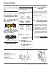
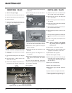
1) Shut the power off.
2) Remove the standard flush door and the
optional bay door, if installed. Open the
bottom louver door.
3) Loosen the 2 screws holding the Burner
ON/OFF switch and bracket to the bottom
louver and lift the assembly out.
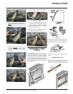
4) Turn the fan base on its side (with the base
facing towards you) and then slide the fan
in towards the rear of the unit. Turn the fan
upright and slip it over the two mounting
studs. Take care not to damage the insula-
tion on the fan base. Ensure that the fan
blades do not rub against the valve
tubing. Diagram 1.
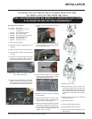
5) Connect fan ground cable to ground lug.
Refer to wiring diagram.
6) Slide the thermodisc/cover assembly into
the bracket clip on the underside of the
firebox. Check that no wire will touch the hot
surfaces. Diagram 2.
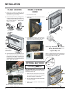
7) Attach the Fan control box to the Burner ON/
OFF control box. Diagram 3.
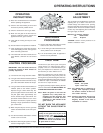
11)Attach the two control boxes to the bottom
louver and tighten the 2 screws on the left
side and 1 screw on the right side.
Secure left side with 2 screws.
Secure right side with one screw.
Secure the 2 boxes together
with one screw.
Hold control box assembly in place and
mark the position of the right side slot
Diagram 1
Diagram 2
Diagram 3: Use the clip & hook on the side
of the control boxes to join them together.
8) Secure the two boxes together with one
screw.
9) Position the control box assembly on the
bottom louver and mark the position of the
slot on the right side bracket.
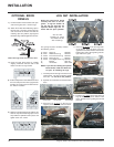
Push hold-down clip onto inside
louver and press tab until it is at
90
o
to
louver.
10)Remove the control box assembly and
push the hold-down clip onto the louver.
Bend the tab until it is at 90
o
to the louver.
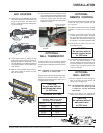
12)Secure the fan wires and power cord by
attaching one of the adhesive backed wire
holder clips (Part #910-199) onto the stove
base. Use the second clip to bundle up the
wires approximately 4" from the control
box. Ensure that there is no interference
with the wires when the louver is closed
and that no wire will touch the hot metal
surfaces or sharp edges.
13)Plug the fan power cord into the rear end of
the receptacle box to provide the maximum
clearance from the louvers.
To Remove the Fan
1) Shut the power off.
2) Reverse the above instructions.
Note: The bearings are lubricated for
life. Do not lubricate them. Make
sure you vacuum the fan area on a
regular basis.
IMPORTANT:
These fans collect a lot of dust from
within your home. Ensure you maintain
these fan motors on a regular basis by
vacuuming out the fan blades and hous-
ing using a soft brush nozzle.