


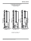

Regency P33R-2 Zero Clearance Rear Vent Direct Vent Gas Fireplace
25
INSTALLATION
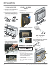
OPTIONAL
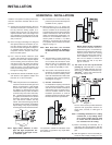
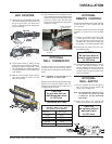
WALL THERMOSTAT
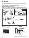
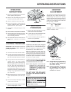
A wall thermostat may be installed if desired,
connect the wires as per the wiring diagram.
Use table below to determine the maximum wire
length.
Note: Preferable if the thermostat is in-
stalled on an interior wall.
Regency offers an optional programmable ther-
mostat but any 250-750 millivolt rated non-
anticipator type thermostat that is CSA, ULC or
UL approved may be used.
CAUTION
Do not wire millivolt
wall thermostat wires
to 120V wire.
14 GA.
16 GA.
18 GA.
20 GA.
22 GA.
50 Ft.
32 Ft.
20 Ft.
12 Ft.
9 Ft.
Recommended Maximum Lead Length
(Two-Wire) When Using Wall
Thermostat (CP-2 System)
Wire Size Max. Length
Thermostat Wire Table
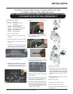
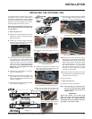
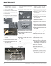
5) Open the bottom louver. Pull the Burner ON/
OFF control box from inside the bottom of the
fireplace and position the slots in the bracket
over the 2 screws on the left side of the
bottom louver. Push down to lock into place.
Tighten the screws.
Burner ON/OFF
control box
Screws on louver
bracket
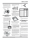
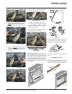
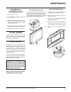
BAY LOUVERS
1) Install top louver by sliding the two bracket
clips into the brackets located on top of the
bay door. See below. The fitted louver
leaves a small gap between faceplate bot-
tom and louver top.
2) Install bottom louver by sliding the two
bracket clips into the brackets located un-
derneath the bay door. Secure with 1 screw
into each Bottom Louver Mounting Bracket
as per diagram below. Use the bottom hole
in the bracket.
3) Slide the valve extension knobs onto the
valve knobs. Match the correct ext. knob
with the valve knob.
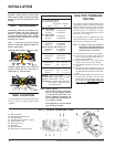
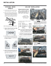
OPTIONAL
REMOTE CONTROL
Use the Regency Remote Control Kit approved
for this unit. Use of other systems may void
your warranty.
The remote control kit comes with a hand held
transmitter, a receiver and a wall mounting
plate.
1) Choose a convenient location on the wall
to install the receiver and the receptacle
box (protection from extreme heat is very
important). Run wires from the fireplace to
that location. Use Thermostat Wire Table.
2) Connect the two wires to the gas valve.
See diagram below.
CAUTION
Do not wire millivolt
remote control wires
to 120V wire.
3) Install 3 AAA alkaline batteries in transmit-
ter and 4 AA alkaline batteries in the
receiver. Install the receiver and its cover
in the wall. Switch the remote receiver to
"remote" mode. The remote control is now
ready for operation.
OPTIONAL
WALL SWITCH
1) Run the supplied 15' of wire through the
right or left side gas inlet opening. Be
careful not to damage wire.
Note: We recommend a maximum of 15'
of wire but if you wish to go with
a longer run, use the Thermostat
Wire Table.
2) Connect the wire to the supplied wall
switch and install into the receptacle box.
CAUTION
Do not wire millivolt
wall switch wire
to 120V wire.