


Regency
®
L676E Direct Vent Gas Fireplace
32
INSTALLATION
INSTALLATION
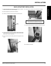
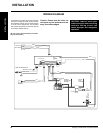
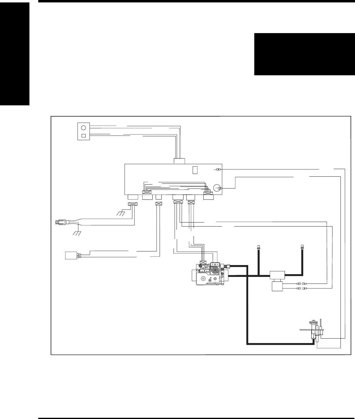
WIRING DIAGRAM
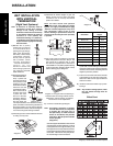
A receptacle is provided on the left hand side
of the unit. 120 Volt AC power must be wired to
the receptacle and the control module plugged
in for the unit to operate fully. The front and
rear burners will operate on low, when the unit
is running on battery back-up.
(Do not cut the ground terminal off under
any circumstances.)
CAUTION: Label all wires prior
to disconnection when servicing
controls. Wiring errors can
cause improper and dangerous
operation.
Caution: Ensure that the wires do
not touch any hot surfaces and are
away from sharp edges.
Black
Orange
Black
Green
Reset Button
Lockout Led
NEUTRAL (white)
LIVE (black)
red
black
J7
ECS MODULE
A
B
D
E
C
2
1
NG/LP
jumper
B
Flame Sensor
Spark Ignitor
yellow
green
white
white
black
orange
BURNER
(REAR)
grey
grey
BURNER
(EMBER)
SECONDARY
MODULATING
COIL
red
black
9V SOLENOID
VALVE
black
MAIN
red
black
red
PILOT
Flame Sensor
Spark Ignitor
orange
yellow
red
black
white
4321
E
V
1
E
V
2
R
.Q
.
A
D
J
.
V
E
N
T
P.O
U
T
M
D
P
in
120V Power Source
Battery