


Regency
®
L676E Direct Vent Gas Fireplace
26
INSTALLATION
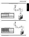
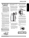
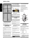
GAS PIPE PRESSURE
TESTING
The appliance must be isolated from the gas
supply piping system by closing its individual
manual shut-off valve during any pressure
testing of the gas supply piping system at
test pressures equal to or less than 1/2 psig.
(3.45 kPa). Disconnect piping from valve at
pressures over 1/2 psig.
The manifold pressure is controlled by a regulator
built into the gas control, and should be checked
at the pressure test point.
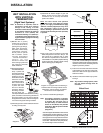
Note: To properly check gas pressure, both
inlet and manifold pressures should
be checked using the valve pressure
ports on the valve.
1) Make sure the unit is turned OFF.
2) Loosen the "IN" and/or "OUT" pressure
tap(s), turning counterclockwise with a
1/8" wide fl at screwdriver.
3) Attach manometer to "IN" and/or "OUT"
pressure tap(s) using a 5/16" ID hose.
4) Turn the unit ON.
5) The pressure check should be carried out
with the unit burning and the setting should
be within the limits specifi ed on the safety
label.
6) When fi nished reading manometer, turn off
the unit, disconnect the hose and tighten the
screw (clockwise) with a 1/8" fl at screwdriver.
Note: Screw should be snug, but do not
over tighten.
PILOT ADJUSTMENT
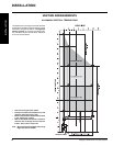
HIGH ELEVATION
This unit is approved in Canada for altitude 0
to 4500 ft. (CAN1 2.17-M91).
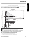
GAS LINE
INSTALLATION
Since some municipalities have additional
local codes it is always best to consult with
your local authorities and the CAN/CGA B149
installation code.
For USA installations follow local codes and/or
the current National Fuel Gas Code, ANSI
Z223.1.
When using copper or fl ex connectors use only
approved fi ttings. Always provide a union so
that gas lines can be easily disconnected for
servicing. Flare nuts for copper lines and fl ex
connectors are usually considered to meet this
requirement.
Important: Always check for gas leaks with a
soap and water solution or gas leak detector.
Do not use open fl ame for leak testing.
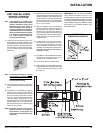
Note: If you have an incorrect fl ame pattern,
contact your Regency
®
dealer for
further instructions.
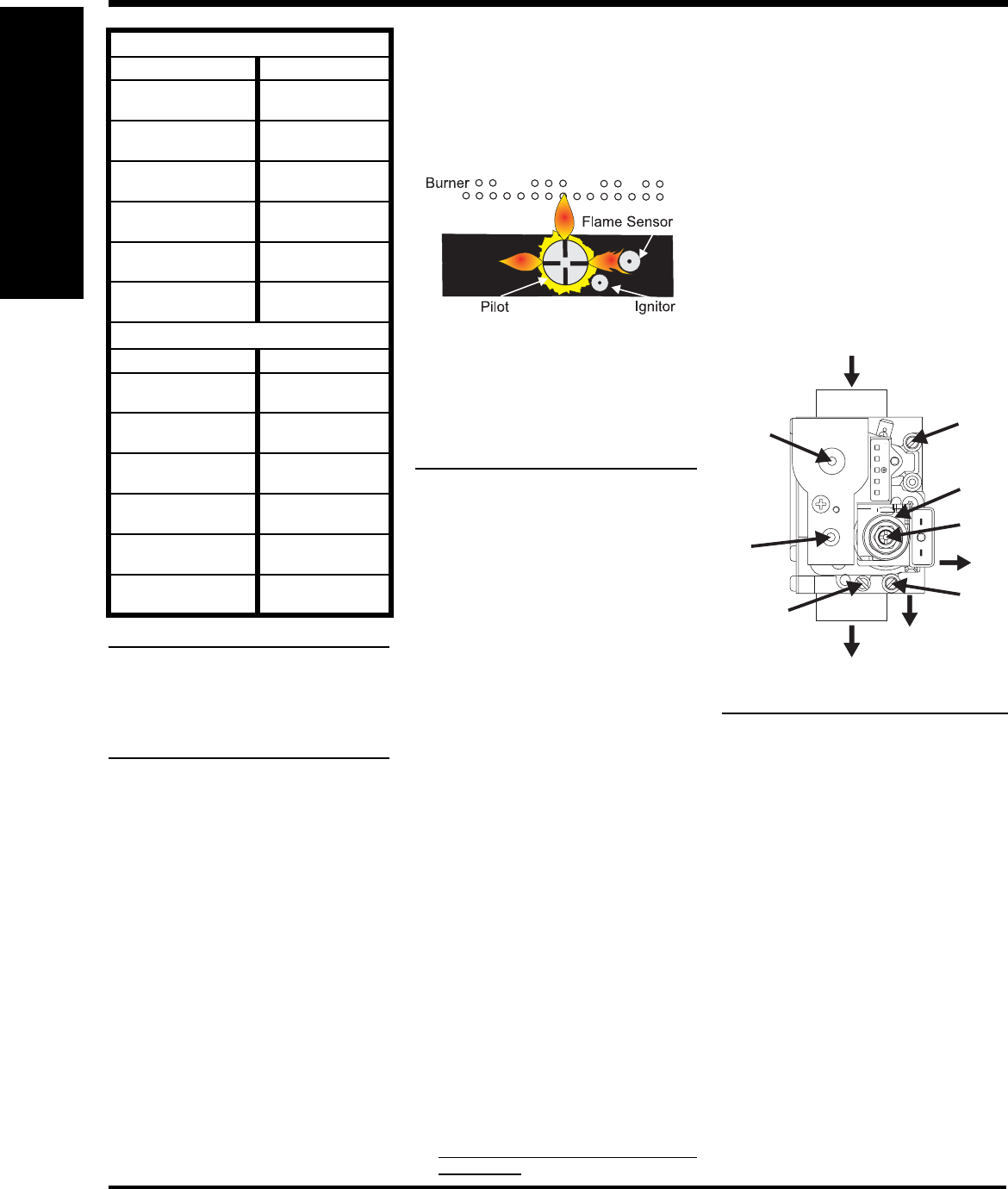
Incorrect fl ame pattern will have small,
probably yellow fl ames, not coming into
proper contact with the rear burner or fl ame
sensor.
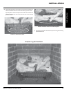
Periodically check the pilot fl ames. Correct
fl ame pattern has three strong blue fl ames:
1 fl owing around the pilot, 1 fl owing around
the fl ame sensor and 1 fl owing across the
burner (it does not have to be touching the
burner).
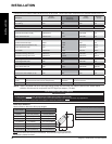
L676E-NG SYSTEM DATA
Min. Supply Pressure 5" WC (1.25 kpa)
Low Setting Man.
Pressure
1.6" WC (0.39 kpa)
Max. Manifold
Pressure
3.5" WC (0.87 kpa)
Orifi ce Size (Front
Burner)
#48 DMS
Orifi ce Size (Back
Burner)
#34 DMS
Minimum Input 11,000 Btu/h
(3.22 kW)
Maximum Input 42,000 Btu/h
(12.3 kW)
L676E-LP SYSTEM DATA
Min. Supply Pressure 12" WC (2.98 kpa)
Low Setting Man.
Pressure
3.6" WC (2.49 kpa)
Max. Manifold
Pressure
10" WC (2.98 kpa)
Orifi ce Size (Front
Burner)
#56 DMS
Orifi ce Size (Back
Burner)
#53 DMS
Minimum Input 9,000 Btu/h
(2.64 kW)
Maxiumm Input 40,000 Btu/h
(11.72 kW)
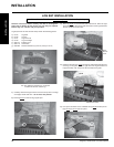
INSTALLATION
AERATION
ADJUSTMENT
The burner aeration is factory set but may need
adjusting due to either the local gas supply or
altitude. Open the air shutter for a blue fl ame or
close for a more yellow fl ame.
In order to adjust the aeration, the logs, grate
and burners will need to be removed to be able
to access the shutters.
Minimum Air Shutter Opening:
NG Front Burner 1/4"
Rear Burner 1/8"
LP Front Burner 5/16"
Rear Burner 1/4"
CAUTION: Carbon will be produced if air shutter
is tightly closed.
Note: Any damage due to carboning
resulting from improperly setting
the aeration controls is NOT covered
under warranty.
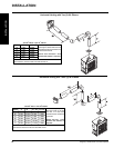
EV1
EV2
R.Q.
ADJ.
P.OUT
MD
4321
Pin
11
8
9
10
1
2
3
4
6
7
5
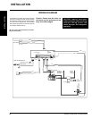
SIT 845 VALVE DESCRIPTION
1) On-Off Solenoid Valve EV1
2) On-Off Solenoid Valve EV2
3) Inlet Pressure Test Point
4) Outlet Pressure Test Point
5) Connection for Pressure Regulator /
Combustion Chamber Compensation
6) Pressure Regulator for Minimum and
Maximum Outlet Pressure
7) Gas Outlet Pressure Electric Modulator
8) Pilot Outlet
9) Main Gas Outlet
10) Side Outlet
11) Main Gas Inlet