


53
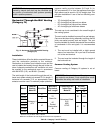
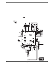
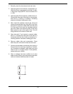
1. Manually close the downstream leak test valve.
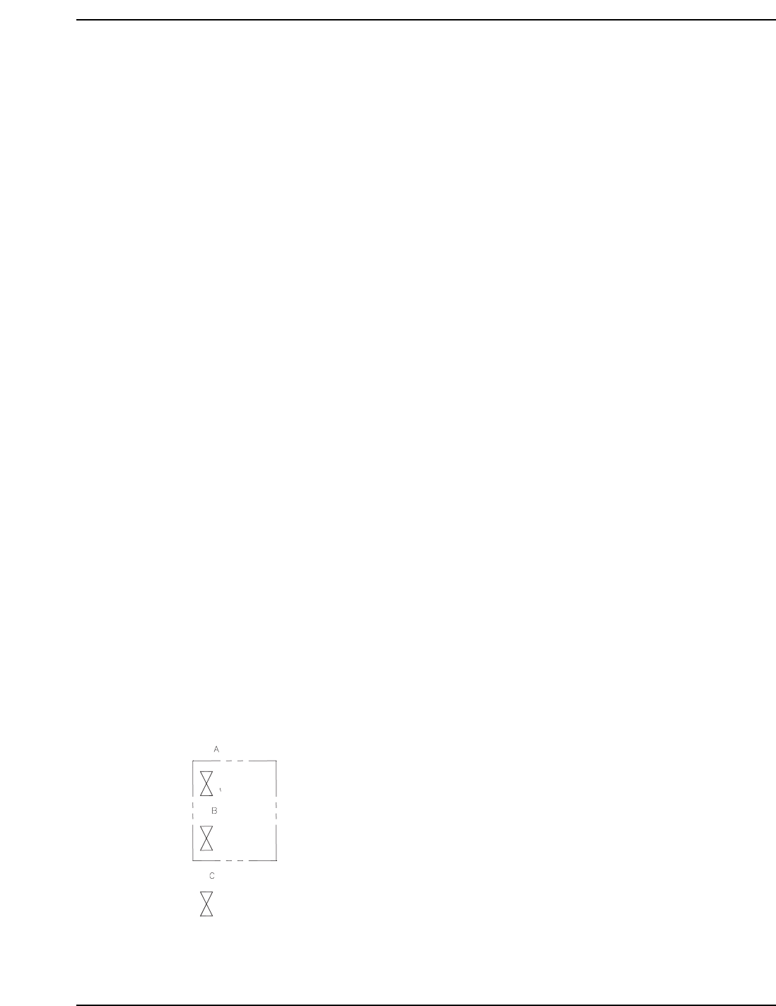
2. Open test point A and connect a manometer to it.
Verify that there is gas pressure and that it is with-
in the proper range (NOTE: must not exceed 14.0
in. WC).
3. Open test point B and connect a rubber tube to it.
Connect the other end of the tube to a manometer
and look for a build-up of pressure. Increasing
pressure indicates a leaking gas valve.
4. Next, close the upstream manual gas valve and
remove the manometer from test point A and from
test point B. Connect a rubber tube from test point
A to test point B and open the upstream manual
gas valve. Make sure that test points A & B have
been opened so as to allow gas to flow. This will
bring pressure to the second valve seat.
5. Open test point C and connect a second rubber
tube to it. Connect the other end of the tube to a
manometer and look for a build-up of pressure. In-
creasing pressure indicates a leaking gas valve.
6. Remove rubber tube and manometers. Close
each test point valve as the tubes are removed.
7. Connect a manometer to each test point (one at a
time) and look for a build-up of pressure. If a build-
up of pressure is detected, check each test point
valve to see if it is tightly closed. If leak persists,
replace test point valve(s).
8. After no leakage has been verified at all valve
seats and test valves, open downstream leak tests
valve and restore electrical power to heater.