


14
b. Not less than the sum of the areas of all vent
connectors in the confined space.
WARNING: Do not use one permanent opening
method if the equipment room is under negative
pressure conditions or the equipment is common
vented with other gas-fired appliances.
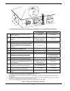
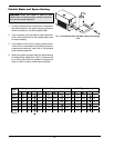
1. Ventilation of the space occupied by the heater
shall be provided by an opening(s) for ventilation
air at the highest practical point communicating
with the outdoors. The total cross-sectional area of
such an opening(s) shall be at least 10% of the
area required in 2. and 3. (below), but in no case
shall the cross-sectional area be less than 10 in.
2
(65 cm
2
).
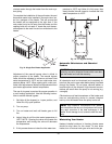
2. For heaters using a barometric damper in the vent
system there shall be a permanent air supply
opening(s) having a cross section area of not less
than 1 in.
2
per 7,000 BTUH (320 mm
2
per kW) up
to and including 1 million BTUH, plus 1 in.
2
per
14,000 BTUH (160 mm
2
per kW) in excess of 1
million BTUH. This opening(s) shall be either
located at or ducted to a point not more than 18 in.
(450 mm) nor less than 6 in. (152 mm) above the
floor level. The duct can also “goose neck” through
the roof. The duct is preferred to be straight down
and terminated 18 in. (450 mm) from the floor, but
not near piping. This air supply opening require-
ment shall be in addition to the air opening for ven-
tilation air required in 1. (above).
3. For heaters not using a barometric damper in the
vent system, and when air supply is provided by
natural air flow from outdoors for a power burner
and there is no draft regulator, drafthood or similar
flue gas dilution device installed in the same
space, in addition to the opening for ventilation air
required in 1., there shall be a permanent air sup-
ply opening(s) having a total cross-sectional area
CAUTION: All combustion air must be drawn from
the air outside of the building; the mechanical equip-
ment room must communicate directly with the out-
doors.
of not less than 1 in.
2
for each 30,000 BTUH mm
2
per kW) of total rated input of the burner(s), and
the location of the opening(s) shall not interfere
with the intended purpose of the opening(s) for
ventilation air referred to in (1). This opening(s)
can be ducted to a point not more than 18 in. (450
mm) nor less than 6 in. (152 mm) above the floor
level. The duct can also “goose neck” through the
roof. The duct is preferred to be straight down 18
in. (450 mm) from the floor, but not near piping.
4. Refer to B149.1 for additional information.
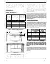
Water Piping
General
The heater should be located so that any water leaks
will not cause damage to the adjacent area or struc-
tures.
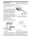
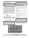
Reversing Water Connections
Follow these instructions to change the water connec-
tions from the left-hand side (standard) to the right-
hand side.
1. Disconnect all electrical power from the heater (if
applicable).
2. Label all electrical connections and conduit lines.
This may include the flow switch, low water cut-off
probe and/or pump.
3. Disconnect or isolate the main gas pipe from the
heater (if applicable).
4. Remove both in/out and return header access
panels by removing all sheet metal screws.
WARNING: Care must be taken to ensure that the
equipment room is not under negative pressure con-
ditions or that the equipment is not common-vented
with other gas-fired appliances.
NOTE: For 87%-efficiency boilers, see special
instructions on page 43.
CAUTION: This heater requires forced water circu-
lation when the burner is operating. See Table G and
Table H for minimum and maximum flow rates and
water pump selection. The pump must be interlocked
with the heater to prevent heater operation without
water circulation.
NOTE: Minimum pipe size for in/out connections is
2
1
⁄2 in. Verify proper flow rates and ΔT as instructed
in this manual.
Canadian Installations