


25
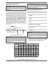
Installer action is required to electrically enable your
heater to operate after making the power connections.
You must make a closed contact connection on Stage
1 connector of the Central Point Wiring (CPW) board
for temperature control connections. This will be done
based on the controller option selected with your
heater order.
1. For Pool and Closed-Loop Water-Source Heat
Pump applications, your heater should be config-
ured to operate in an on-off firing mode. This
means that you will connect a single-pole control
to stage one of the CPW board. Then jumper the
remaining firing stages. For example, if your
heater is a Model 1532A, you will jumper stages
two, three and four. Then your heater will either be
on at full fire, or it will be off.
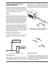
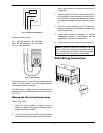
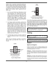
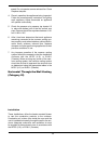
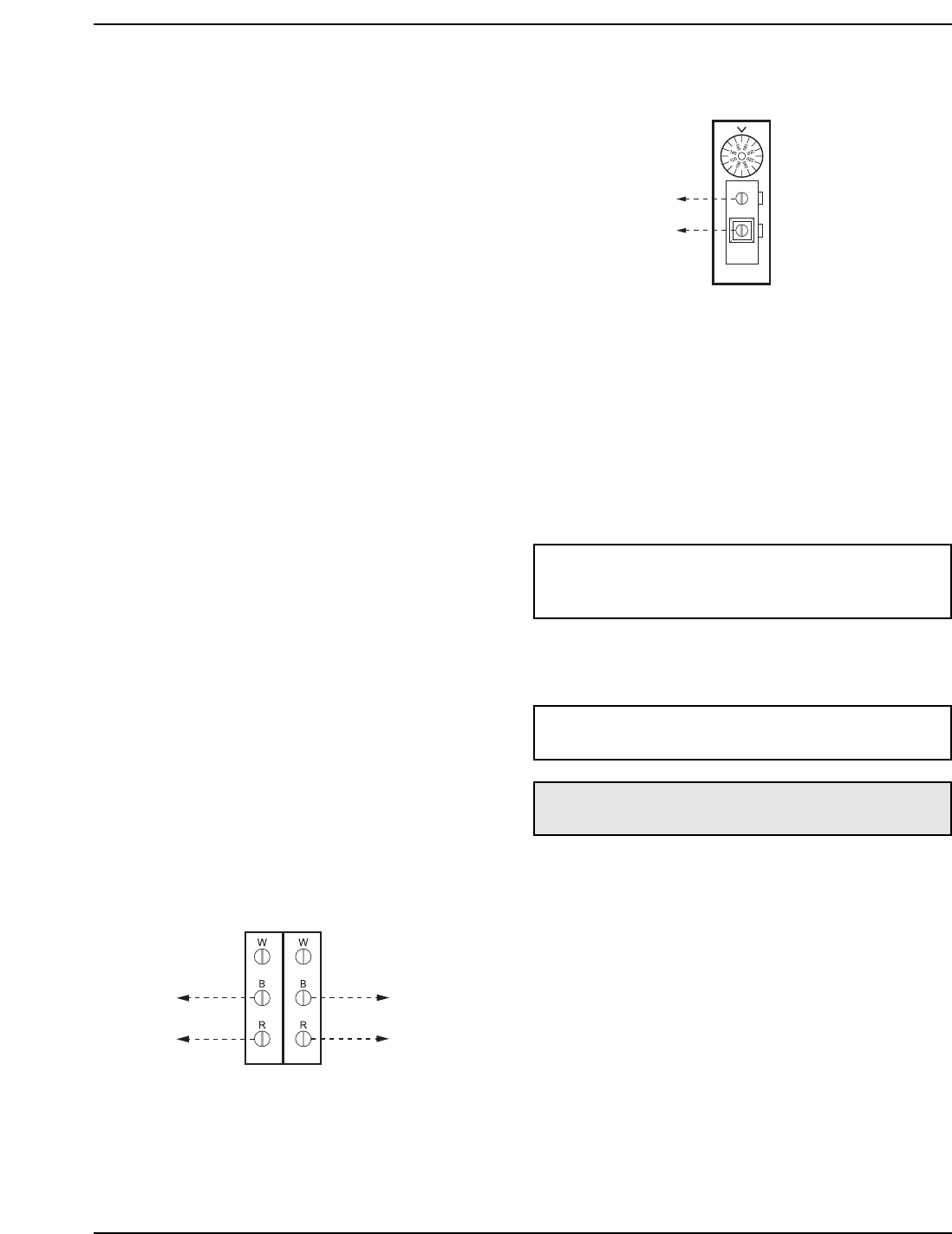
2. For 2-stage controller connections, connect each
stage of the control to the corresponding stage of
the CPW board in the heater, i.e., stage 1 of the
heater to stage 1 of the control; stage 2 of the
heater to stage 2 of the control, as shown in Fig.
22 and Fig. 25. Set the operating control to the
set-point at which you want the heater to maintain.
Ensure that the sensing bulb of the control is at the
point in the system that will best maintain the tem-
perature you want. For example, when you are
heating a tank of water, you want the operating
control sensor bulb in the tank.
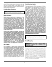
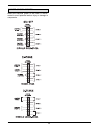
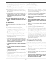
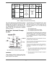
3. For single-stage controller connections, attach the
stage 1 connections on heater 1 to the tankstat per
Fig. 26.
Heater must be electrically grounded in accordance
with the NEC, and CSA C22.1 C.E.C. Part 1 in
Canada.
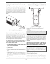
2-STAGE
TANKSTAT
STAGE 1
CONNECTION
STAGE 2 CONNECTION OR
STAGE 1 CONNECTION
OF HEATER 2
ATTACH STAGE 1 CONNECTIONS ON HEATER
TO STAGE 1 CONNECTION ON TANKSTAT.
ATTACH STAGE 2 CONNECTIONS OR
STAGE 1 CONNECTION OF HEATER 2
TO STAGE 2 CONNECTIONON TANKSTAT
AS SHOWN IN THE DIAGRAM.
Fig. 25: 2-Stage Tankstat
SINGLE
STAGE
TANKSTAT
STAGE 1
CONNECTION
ATTACH STAGE 1 CONNECTIONS
ON HEATER TO THE SINGLE STAGE
TANKSTAT AS SHOWN IN THE DIAGRAM ABOVE.
Fig. 26: Single-Stage Tankstat
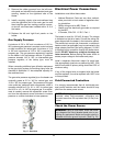
Consult the wiring diagram shipped with the heater in
the instruction packet or at the end of this section. The
stage-selector terminals are for the remote tank con-
trol through the heater’s 24 VAC transformer. DO NOT
attach any voltage to the stage-selector terminals.
Before starting the heater, check to ensure proper volt-
age to the heater and pump.
Venting
General
Appliance Categories
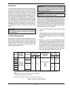
Heaters are divided into four categories based on the
pressure produced in the exhaust and the likelihood of
condensate production in the vent.
Category I – A heater which operates with a non-pos-
itive vent static pressure and with a vent gas tempera-
ture that avoids excessive condensate production in
the vent.
Category II – A heater which operates with a non-pos-
itive vent static pressure and with a vent gas tempera-
ture that may cause excessive condensate production
in the vent.
NOTE: If any of the original wire supplied with the
heater must be replaced, it must be replaced with
similar sized 105°C wire or its equivalent.
NOTE: For 87%-efficiency boilers, see special
instructions on page 43.
CAUTION: Proper installation of flue venting is criti-
cal for the safe and efficient operation of the heater.