


43
87%-Efficiency Boilers –
Special Instructions
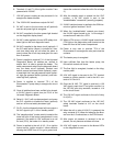
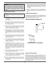
Water Piping
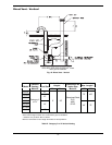
An 87%-efficiency boiler requires a minimum inlet
water temperature of 120ºF (49ºC) to prevent exces-
sive condensation in the combustion chamber. An
87%-efficiency boiler operated with an inlet tempera-
ture of less than 120ºF (49ºC) must have a manual
bypass or an approved low-temperature operation
system to prevent problems with condensation. A man-
ual bypass, shown in Fig. 15, must be piped into the
system at the time of installation. This piping is like a
primary/secondary boiler installation with a bypass in
the secondary boiler piping. Raypak strongly recomm-
NOTE: The constructions of the 84%- (standard)
and 87%-efficiency (optional) boilers are very similar,
and they are installed to the same requirements,
except as noted in this section.
ends that a thermometer be placed into the boiler inlet
piping next to the in/out header to facilitate tempera-
ture adjustment. Inlet water temperatures below 120ºF
(49ºC) can excessively cool the products of combus-
tion, resulting in condensation on the heat exchanger.
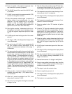
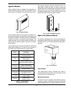
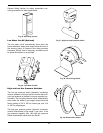
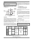
Venting
Appliance Categories
See Table P for appliance category requirements for
the 87%-efficiency Hi Delta.
CAUTION: Proper installation of flue venting is criti-
cal for the safe and efficient operation of the boiler.
NOTE: For additional information on appliance cat-
egorization, see appropriate code NFGC (U.S.) and
B149.1 (Canada), or applicable local building codes.
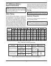
20°F T 30°F T 40°F T Min. Flow Max Flow
Model
No.
gpm
P (ft) gpm P (ft) gpm P (ft) gpm P (ft) Tgpm P (ft) T
992AE 86 5.6 57 2.5 43 1.4 43 1.4 40 132 13.1 13
1262AE 110 10.3 73 4.6 55 2.6 55 2.6 40 132 14.8 17
1532AE 132 16.5 89 7.6 67 4.3 67 4.3 40 132 16.5 20
1802AE N/A N/A 104 11.5 78 6.5 78 6.5 40 132 18.3 24
2002AE N/A N/A 116 14.8 87 8.5 87 8.5 40 132 19.0 26
2072AE N/A N/A 120 15.8 90 9.1 90 9.1 40 132 19.0 27
2342AE N/A N/A N/A N/A 102 12.9 102 12.9 40 132 21.4 31
Note: Basis for minimum flow is 40°F T. Basis for maximum flow is 132 gpm.
Combustion
Air Supply
Exhaust
Configuration
Heater Venting
Category
Certified
Materials
Combustion Air
Inlet Material
Vertical Natural Draft
Venting
II
From Inside Building
(Non-Direct Venting)
Horizontal Through-
the-Wall Venting
IV
AL29-4C
Stainless Steel
(Gas Tight)
Vertical Natural Draft
Venting
II
From Outside Building
(Direct Venting)
Horizontal Through-
the-Wall Venting
IV
AL29-4C
Stainless Steel
(Gas Tight)
Galvanized Steel
PVC
ABS
CPVC
Table O: Heater Rate of Flow and Pressure Drop
Table P: Category Determination for Venting Purpose and Venting Arrangement