


16
Failure to exceed 105ºF (41ºC) within 7 minutes may
result in the premature failure of the hot surface ignit-
er, remote flame sensor, burners and heat exchanger.
It can cause operational problems, bad combustion,
sooting, flue gas spillage and reduced service life of
the vent system. The bypass allows part of the heater
discharge water to be mixed with the cooler heater
return water to increase the heater inlet temperature
above 105ºF (41ºC). This precautionary measure
should prevent the products of combustion from con-
densing in most installations. Warranty claims will be
denied when condensation occurs.
Cold water operation issues are applicable to both
cold water start and cold water run applications. Cold
water operation for 7 minutes or less on start-up is
acceptable. Where cold water starts will last longer
than 7 minutes or where cold water operation is con-
tinuous, provisions must be made to mix higher tem-
perature outlet water with the colder inlet water and
thereby raise the inlet temperature to at least 105ºF
(41ºC) within the 7-minute time limit.
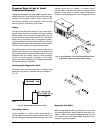
Cold Water Starts
Frequent (more than once a week) cold water starts,
wherein the inlet water temperature remains below
105ºF (41ºC) for more than 7 minutes, must have cold
water start protection. Known protection methods con-
sist of mixing heated outlet water with the inlet water
with a bypass to raise the inlet to 105ºF (41ºC) or high-
er. Once the system is heated up and has return water
temperatures of 105ºF (41ºC) or higher, the mixing of
outlet water with inlet water is no longer needed and
the bypass can be shut off. If the bypass is not shut off
as the system heats up, the outlet temperature may
continue to climb and actuate the high limit, thereby
shutting down the heater. Thus an automatic valve
system, such as a three-way proportional valve or a
modulating two-way valve to control the bypass,
should be utilized.
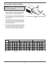
Cold Water Run
Cold water run differs from cold water start in that the
system water entering the heater remains below 105ºF
(41ºC) continuously. Typically, this is the case in swim-
ming pool heating and water source heat pump appli-
cations as well as some others. If the system water is
kept in a narrow temperature range, a permanent
manual bypass can be employed and manually adjust-
ed to achieve an inlet temperature of 105ºF (41ºC) or
higher. An injector pump arrangement may also be uti-
lized to keep the heater loop at or above 105ºF (41ºC).
An injector pump approach has the added value of
being able to adjust to changes in the system water
coming back to the heater take-off.
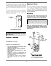
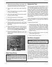
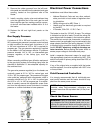
Temperature & Pressure Gauge
The temperature and pressure gauge is factory-
mounted in the in/out header.
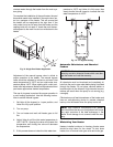
Hydronic Heating
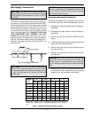
Pump Selection
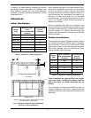
In order to ensure proper performance of your heater
system, you must install a correctly sized pump. Ray-
pak recommends using a 20°F ΔT as design ΔT. (ΔT is
the temperature difference between the inlet and out-
let water when the heater is firing at full rate). If a ΔT
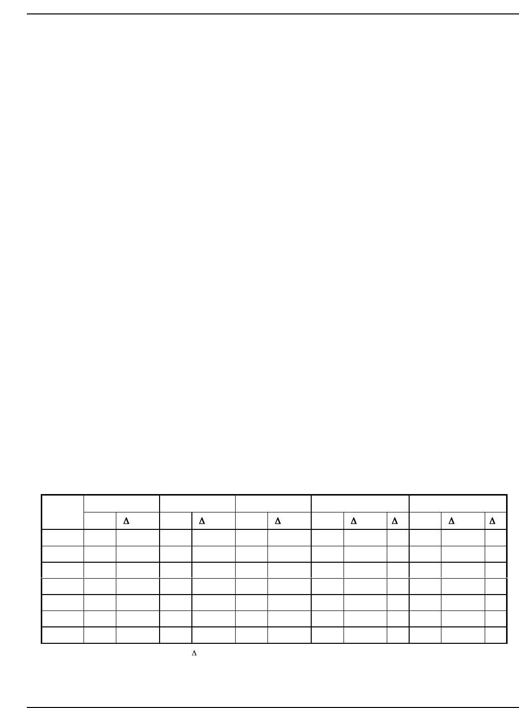
of larger than 20°F is necessary, see Table G and
Table H for flow rate requirements.
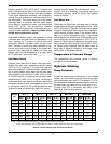
Table G: Heater Rates of Flow and Pressure Drops
20°F
T30°FT40°F
T
Min. Flow Max Flow
Model
No.
gpm
P (ft)
gpm
P (ft)
gpm
P (ft)
gpm
P (ft) T
gpm
P (ft) T
992A 83 5.2 55 2.3 42 1.3 42 1.3 40 132 13.1 13
1262A 106 9.6 71 4.3 53 2.4 53 2.4 40 132 14.8 16
1532A 129 15.7 86 7.1 64 4.0 64 4.0 40 132 16.5 19
1802A N/A N/A 101 10.7 76 6.0 76 6.0 40 132 18.3 23
2002A N/A N/A 112 13.8 84 7.9 84 7.9 40 132 19.0 25
2072A N/A N/A 116 14.8 87 8.5 87 8.5 40 132 19.0 26
2342A N/A N/A 132 21.4 98 12.1 98 12.1 40 132 21.4 30
Notes: 1. Basis for minimum flow is 40°F T. Basis for maximum flow is 132 gpm.
2. Rear-mounted pumps may provide higher flow rates on smaller models than the system requirements