


15
5. Remove all plumbing fittings to the header. This
will include both inlet and outlet water pipe unions
and the pressure relief valve and drain piping.
6. Remove limits, control bulbs and/or thermocou-
ples.
7. Remove the eight flange nuts and the in/out head-
er from the left-hand side.
8. Remove the eight flange nuts and the return head-
er from the right-hand side.
9. Reverse the headers to the new location.
10. Install NEW red beveled O-rings flush against both
tube sheets with the bevel facing outward.
11. Push the header firmly against the O-rings. Install
and tighten the flange nuts onto the stud bolts until
finger tight.
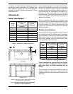
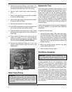
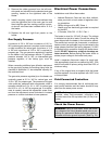
12. Slowly tighten the flange nuts, starting from the
center nut (number 1) in Fig. 9 and working se-
quentially around the header as indicated. Torque
all nuts to 25 ft/lb. DO NOT OVER-TIGHTEN.
13. Re-route the capillary(s), wiring etc. to the new
location, adding thermal paste and shim to the
capillary well.
Fig. 9: Torque Sequence
Relief Valve Piping
WARNING: Pressure relief valve discharge piping
must be piped near the floor and close to a drain to
eliminate the potential of severe burns. Do not pipe
to any area where freezing could occur. Refer to
local codes.
Hydrostatic Test
Unlike many types of heaters, this heater does not re-
quire hydrostatic testing prior to being placed in opera-
tion. The heat exchanger has already been factory-
tested and is rated for 160 psi operating pressure.
However, Raypak does recommend hydrostatic test-
ing of the piping connections to the heater and the rest
of the system prior to operation. This is particularly
true for hydronic systems using expensive glycol-
based anti-freeze. Raypak recommends conducting
the hydrostatic test before connecting gas piping or
electrical supply.
Leaks must be repaired at once to prevent damage to
the heater. NEVER use petroleum-based stop-leak
compounds.
To perform hydrostatic test:
1. Connect fill water supply. With bleed valve open,
fill heater with water. When water flows from bleed
valve, shut off water. Close bleed valve. Carefully
fill the rest of the system, making sure to eliminate
any entrapped air by using high-point vents. Close
feed valve. Test at standard operating pressure for
at least 24 hours.
2. Make sure constant gauge pressure has been
maintained throughout test.
3. Check for leaks. Repair if found.
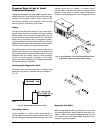
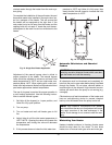
Cold Water Operation
A heater operated with an inlet temperature of less
than 105ºF (41ºC) must have a manual bypass or an
approved low-temperature operation system to pre-
vent problems with condensation. A manual bypass,
shown in Fig. 15, must be piped into the system at the
time of installation. This piping is like a primary/sec-
ondary boiler installation with a bypass acting as the
secondary boiler piping. Raypak strongly recommends
that thermometer(s) be placed into the heater piping
next to the in/out header to facilitate temperature
adjustment. Inlet water temperatures below 105ºF
(41ºC) can excessively cool the products of combus-
tion, resulting in condensation on the heat exchanger
and in the flue.
CAUTION: Damaging internal condensation may
occur if the heater inlet water temperature does not
exceed 105ºF (41ºC) within 7 minutes of start-up.